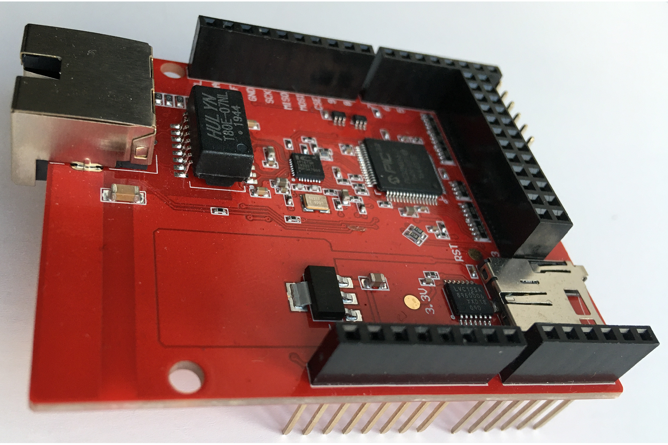
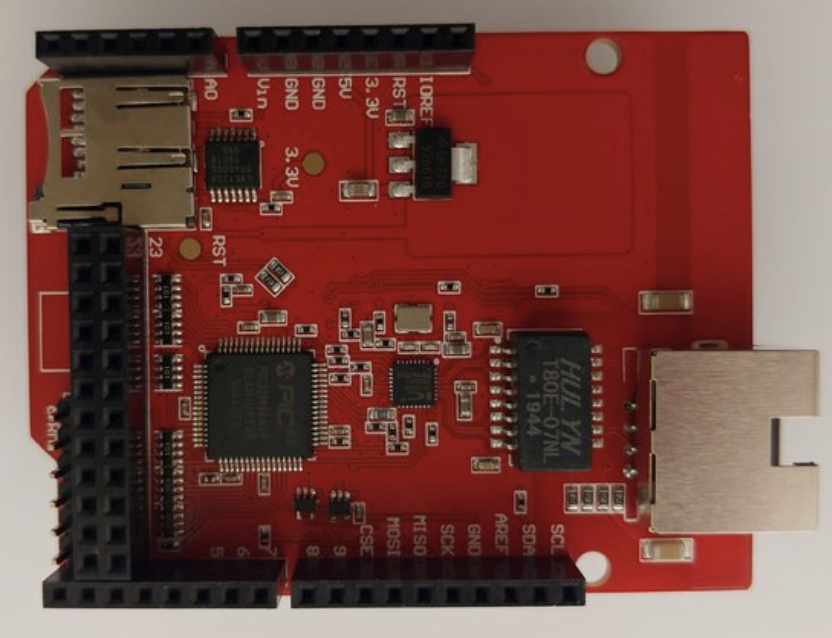
Arduino Ethernet Shield powered by the PIC32MX controller
Angelu (Elsofgel), a Canadian-based electrical engineer has developed an Arduino shield to implement an SPI to Ethernet Interface (SEI) on the PIC32 microcontroller. While it seems very similar to the Wiznet’s chips, the major difference being that it is a software implementation and the physical layer (PHY) is an external device.
Angelu (Elsofgel), a Canadian-based electrical engineer has developed an Arduino shield to implement an SPI to Ethernet Interface (SEI) on the PIC32 microcontroller. While it seems very similar to the Wiznet’s chips, the major difference being that it is a software implementation and the physical layer (PHY) is an external device.
It interfaces the host controller via SPI interface with a clock speed up to 20MHz, and one extra interrupt line. One 8 bit GPIO port and one 15bit GPIO port that can be controlled by the host controller. The SPI implementation has a “Register Monitor Interface” that serially outputs most of the register’s values to a PC application which is very helpful during development.
He also wrote two host controller open-source applications in for the device. The first display’s sensor data like outdoor temperature, sensor location time, power grid frequency e.t.c., which you can find here. The other one just shows a very cute picture of a cat.
“There are three versions of the SEI, one implemented on the PIC32MX664F064 with 20K dedicated to the Ethernet Rx/Tx buffers, one implemented on PIC32MX695F512 with 103k of Rx/Tx buffers and one on PIC32MZ microcontroller that offers symmetric encryption. There is a version of each of the three that connects to a network switch KSZ8863RLL instead the classic PHY chip,” notes Angelu.
Though the PIC32MZ microcontroller implementation is not ready at the moment of writing, he also plans to build a version with VLAN capability.
There is no library for the shield yet, so the host controller accesses the registers directly in the examples above. Furthermore, the cat example is driven by an Xmega controller overclocked to 40MHz and the SPI running at 20MHz while writing, and 10MHz while reading.
The features of the shield include:
- Extra 8 + 15 I/O pins that can be controlled via the SPI interface
- Register Monitor Interface via a UART Tx pin that can be useful when debugging the Arduino code
- 20 kB receive/transmit total buffer memory
- 4 independent multi-subnet sockets
- 20MHz SPI mode 0, 1, 2 or 3
- Protocols: ARP, IPv4, ICMP, UDP, TCP, DHCP
- PING reply algorithm
- Interrupt System
- PHY with Auto MDI-X capability
- MicroSD socket onboard
- 3.3 – 5V compatible
The PCB design is open source, and the User manual, schematics, and 3D pdfs are all available on Github. The shield is currently available on Tindie for $22 and some information about it is also available there.


