Circuit provides reverse-battery connection protection
A universal problem in battery-operated devices is the threat of damage when an end-user (never an engineer) inserts the battery backward. You can avoid damage by inserting a single diode or by using a diode-bridge configuration, but those fixes waste power and reduce the supply voltage by adding one or two diode drops between the battery and the supply rail.
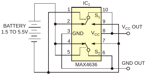
A universal problem in battery-operated devices is the threat of damage when an end-user (never an engineer) inserts the battery backward. You can avoid damage by inserting a single diode or by using a diode-bridge configuration, but those fixes waste power and reduce the supply voltage by adding one or two diode drops between the battery and the supply rail. An alternative solution not only protects against battery-reversal damage but also automatically corrects the reversal (Figure 1). To eliminate the voltage drops associated with discrete diodes, a low-on-resistance, DPDT (double-pole, double-throw) switch serves as a full-wave rectifier. When you insert the battery with the correct polarity as shown, the upper switch, S1, is in its normally closed state, because its control pin is in its low state. The resulting connection from Pin 2 to Pin 10 provides a low-impedance path from the battery to the VCC terminal. Conversely, the lower switch, S2, closes its normally open terminal (not as shown) because its control pin is in its high state. The resulting path from Pin 7 to Pin 6 connects the battery’s negative terminal to ground.
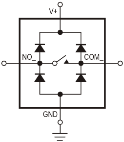
The ESD-protection diodes in IC1 guarantee start-up and act as a full-wave rectifier (Figure 2). MOSFETs internal to the analog switch turn on when the battery voltage exceeds 1 V. Their less-than-20-nsec turn-on time enables the circuit to maintain normal operation by quickly swapping the leads of a reversed-polarity battery connection. The circuit resistance is proportional to the battery voltage. When the circuit operates from four NiCd, NiMH, or alkaline cells, the resistance in each leg of the rectifier is 2.5 Ω (5 Ω total). Operation with a two-cell battery (2.4 to 3 V) yields a total resistance of 10 Ω. IC1 is rated for operation to 5.5 V with 30-mA continuous current, making the circuit useful for cordless phones, portable audio equipment, handheld electronics, and other light- to medium-current applications. IC1‘s miniature 10-pin µMAX package takes less space than four through-hole signal diodes and is almost as small as two SOT-23 dual signal diodes.
source: EDN