How to Create Inverted Silkscreen in Cadsoft Eagle
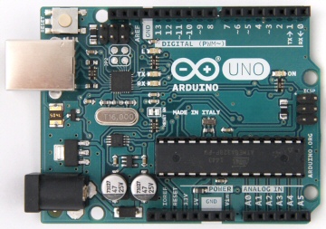
If you’re one of EAGLE CAD fans, and you were wondering how some boards like Arduino boards have what's called a negative silkscreen, hollow rectangles or shapes by text or logo, then you will learn how to do it with Ishaan’s video tutorial. Ishaan used a ULP called “negasilk.ulp” in his tutorial.
If you’re one of EAGLE CAD fans, and you were wondering how some boards like Arduino boards have what’s called a negative silkscreen, hollow rectangles or shapes by text or logo, then you will learn how to do it with Ishaan’s video tutorial.
Ishaan used a ULP called “negasilk.ulp” in his tutorial. It is written by Christian Bohrer, and it can be downloaded here.
We’ve tested this trick in ElectronicsLab using these steps:
- Adding some texts on layer 41tRestrict.
- Drawing a rectangular polygon in 1Top layer with width 8 mil (according to Ishaan, this ULP accepts only this width), and don’t forget to hit ratsnest.
- Run negasilk.ulp.
- A script file is generated in the same directory of your .brd file, open it and make the following modification using any text editor (adding layer 21 line).
Set Wire_Bend 2;
LAYER 21;
GRID MM; - Finally, delete the unwanted polygon and text from layer 41 and layer 1.
You can see these steps in the following GIF(click to view):