Duane Bester has built a GPS Tracker From Scratch Using 3 Arduino boards to make a GPS tracker and a data logger. A flash of idea came to him, to combine the new Arduino Nano 33 BLE Sense with an SD card and GPS module for a project that records GPS and IMU data. So he opted to buy the Nano 33, the MKR Mem Shield, and the MKR GPS Shield and couple all of them together. He later found out that these boards aren’t footprint-compatible, so He combined them with a breadboard. It took time to get all the plugins installed and everything connected correctly. The biggest challenge he faced was the GPS module, and he says “It really helps to start debugging the GPS’ example code outside; where the satellite signal is available.” After successfully vetting the Prototype code for the arduino, he went ahead to build a custom PCB.
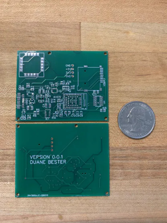
For the PCB design, he used easyeda to build his custom PCB. The first thing he did was obtaining the schematics from the Nano 33, the MKR Mem Shield then the MKR GPS Shield. The schematic was easy to access via Github. Since they are Eagle schematic files, the Eagle trial version was used for an in-depth analysis. After that, he copied the full Nano 33 BLE schematic as it is, as well as matching up the component names and numbers. He then included the GPS module then he had to figure out how to program through J-Link. To ensure it’s optimal, he went on to send off the design to PCBWay to be built and coupled. This was a smooth process, with some questions concerning the part name and orientation. Few weeks later he received the plan PCB boards in the mail, then six weeks later he got the fully assembled PCB boards.
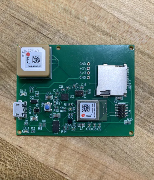
When he wanted to flash the Arduino bootloader, he purchased the J-Link EDU Mini cable to be used for programming the custom board and all the J-Link drivers installed. He finally flashed the bootloader through nRF Connect, and it worked. An Arduino Nano would pop up and connect to his MacBook when he plugged in the USB cable. However, during the course of the build, he realized he had made a few mistakes in reverse engineering, the board. The mistakes he made includes:
The Nano 33 schematic has a Do Not Populate (DNP) for a pull-up resistor on the RESET pin. I should have added test points for this resistor as well. I ended up hand-soldering a 4.7K. This stopped my board from auto-resetting every second (could also adjust the UICR to disable the RESET pin).
The schematic shows a 1M Ohm resistor connecting the USB shield to the ground. But the Eagle file shows 330 Ohm , which should be 330 Ohms. (There is tons of debate and trade-offs here)
He messed up wire with the gesture sensor, so the sensor didn’t work. However, it still measured RGB colors.
He was able to fix the issues mentioned above.
To make the device portable, He added a battery connection, LiPo charging, and load sharing. The device was further equipped with a 5V and 3.3V power rail to power external devices. After making more research, He decided to add more decoupling capacitors and various connectors (including GPIO). Finally, he sent the new design with a more compact PCB layout to PCBWay, and he is currently waiting on the boards to get back. For more information about the project, visit the project page here


![From Sand to Circuits – How Intel makes integrated circuits [PDF]](https://www.electronics-lab.com/wp-content/uploads/2016/11/intel.jpg)
