How to Program an Ultrasonic Humidifier
Author: Marian Hryntsiv, Senior Technical Documentation Apps Engineer, Renesas Electronics 1. System Overview Nowadays, humidifiers have become popular devices.
Author: Marian Hryntsiv, Senior Technical Documentation Apps Engineer, Renesas Electronics
1. System Overview
Nowadays, humidifiers have become popular devices. They are frequently used to increase the level of humidity in rooms in many houses across continents. Ultrasonic humidifiers use a piezoelectric transducer to create a high-frequency mechanical oscillation in a water film. This forms an extremely fine mist of droplets, about one micron in diameter, that is quickly evaporated into the airflow.
SLG47105 can be used to implement the basic functionality of the ultrasonic humidifier (see Figure 1).
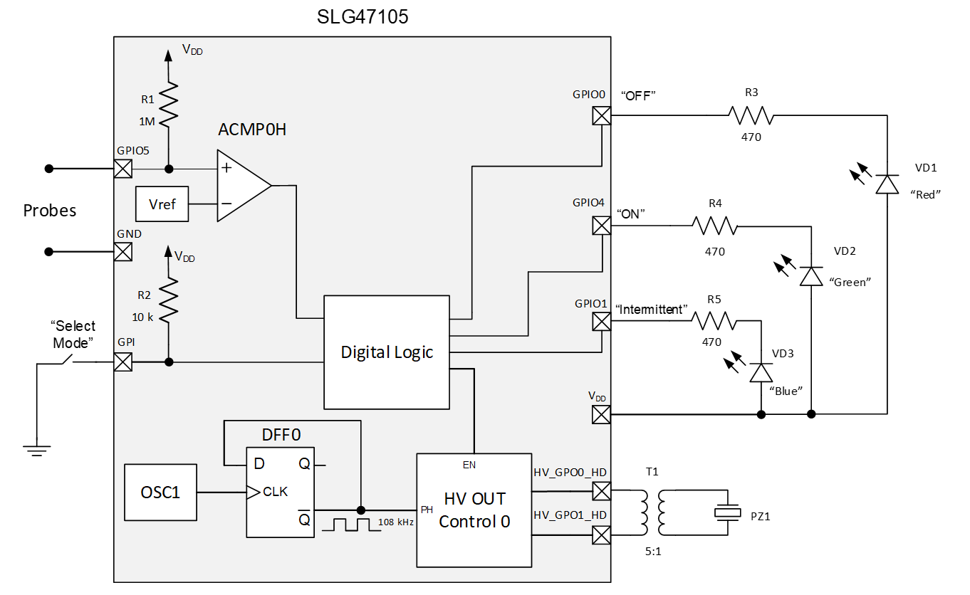
In this article, the piezoelectric transducer with a resonant frequency equal to 108 kHz is used. SLG47105 has an oscillator OSC1 with a flexible divider, which allows to accurately set the desired frequency.
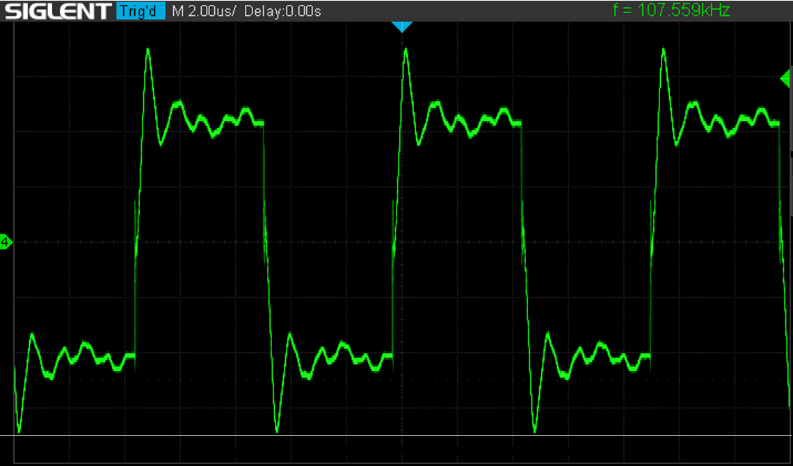
Additionally, D Flip-Flop (DFF0) is used to get a 108 kHz clock signal from the oscillator’s output signal. HV_GPO0_HD and HV_GPO1_HD are high voltage and high drive pins that allow to get the desired output power (see pins output signal in Figure 2). A transformer has a turns ratio of 5:1. It allows getting from 5 V the required voltage for the operation of the piezo converter.
2. GreenPAK™ Design
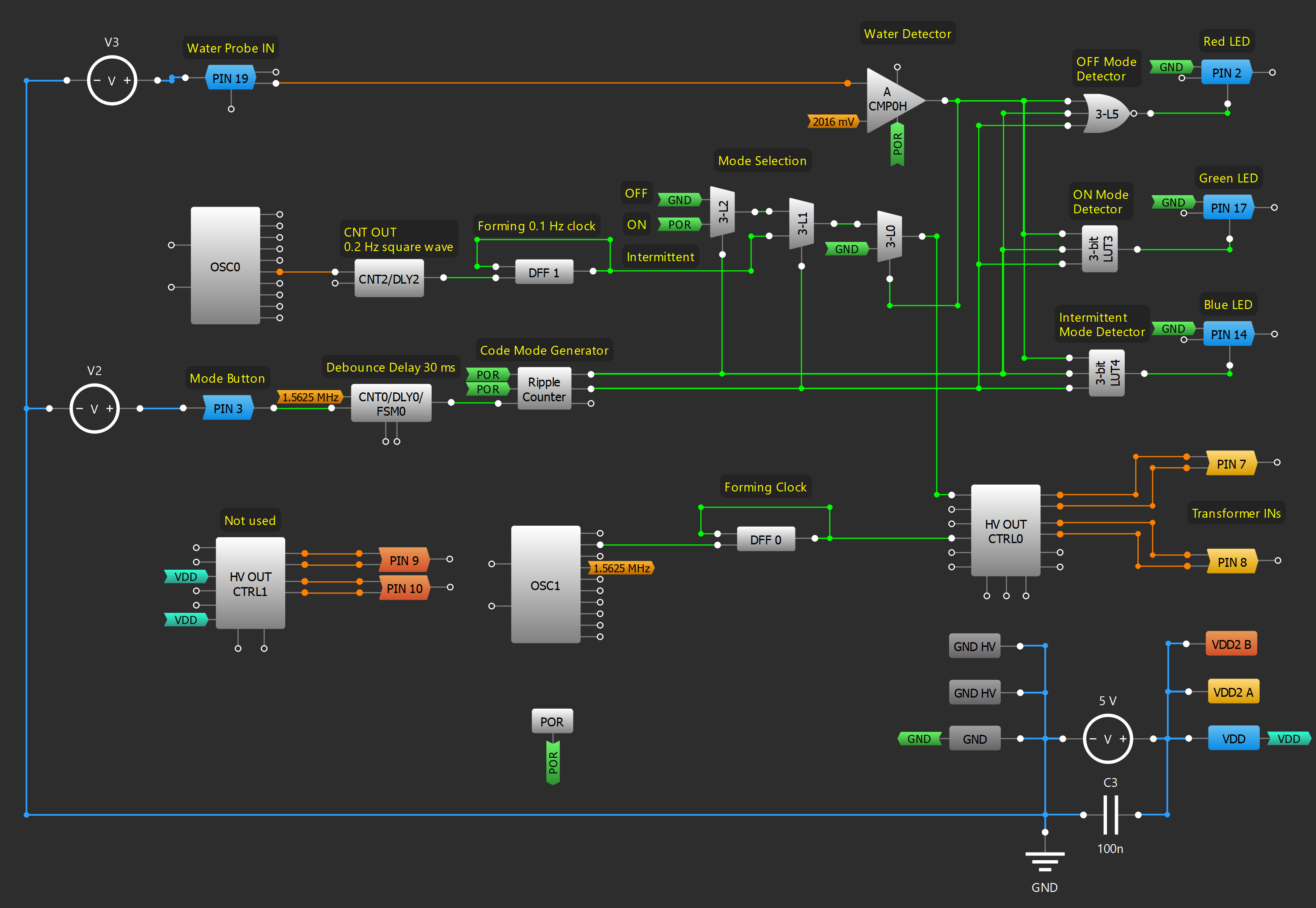
Figure 3 shows an internal design of the project created in GreenPAK Designer software (a part of Go Configure™ Software Hub). The complete design file can be downloaded here
2.1 Humidifier Modes of Operation
For flexibility in use, the humidifier has three modes of operation: OFF state, ON state, and intermittent operation. The last mode means that the humidifier works for 5 s and then waits for 5 s, and so on alternately. Digital logic macrocells were used to implement these modes. An external button is used to select a mode of operation. It produces noisy output oscillations due to switch bouncing. To eliminate that noise 30 ms delay is used. With every pressing of the button, Ripple Counter generates a digital code for the appropriate mode. There are three modes of work and, respectively, three digital codes: 00, 01, 10. The output signal from Ripple Counter goes to select inputs of cascaded multiplexers (3-L1 and 3-L2) and thus allows to choose which signal will pass to the output: LOW level signal (OFF mode), HIGH level signal (ON mode), or clock signal with frequency 0.1 Hz (Intermittent mode). And, if there is water inside the humidifier, multiplexer 3-L0 allows passing one of the signals from cascaded multiplexers on the Enable input of the HV OUT Control macrocell.
For Intermittent mode, Reset Counter2 and DFF1 form a 0.1 Hz clock signal.
LEDs indicate mode of operation: red LED – OFF mode, green LED – ON mode, blue LED – Intermittent operation. LUT3, LUT4, and LUT5 detect each mode and turn on the corresponding LED with the help of pins. Pins work as 3-state outputs. When a HIGH level signal appears on the pin’s Output Enable input then the pin goes from a high impedance state to a logic 0 state. This LOW-level signal causes the corresponding LED to turn on. For a more advanced experience, when the humidifier is in OFF mode, it can be used as a night light with a red glow.
2.2 Water Level Detection
One of the negative features of ultrasonic humidifiers is that the piezoelectric disc can be destroyed if the humidifier runs out of water. That’s why it is very important to implement an automatic shut-off of the humidifier when the disc is dry. In this project, probes immersed in water were used. When there is no water between the probes, an analog comparator’s output is HIGH, which disables high voltage pins and stops piezo disc oscillation.
3 Humidifier Prototyping
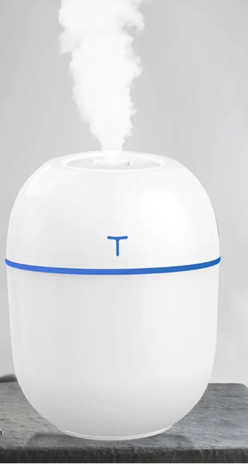
The humidifier developed in this project can replace a finished product on the market. For this purpose, a portable ultrasonic humidifier was bought and analyzed (see Figure 4).
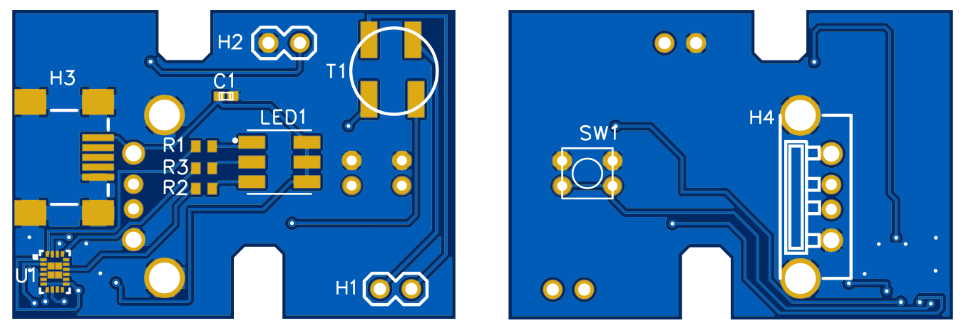
The dimensions of the PCB and the location of the main components of interaction with the user were measured. Based on these data, the PCB for the SLG47105-based humidifier was developed (see Figure 5).
The humidifier based on the SLG47105 has some advantages over the purchased humidifier because it has water level detection. This function is very important because it can prevent the humidifier from failing. In addition, the number of electronic components has been reduced when using SLG47105.
4. Conclusions
The SLG47105 has two high drive H-Bridges, which can be used as four Half Bridges or two Full Bridges. One of the Full Bridges is used in this project to drive the ultrasonic piezoelectric disc. Its resonant frequency is set by the oscillator and flexible divider. This allows the piezoelectric disk to oscillate and form cool fog. Additionally, the availability of many versatile digital macrocells made it possible to add some additional features, like detection of no water, backlight control, and three operation modes. This design can be a functional replacement for popular standard portable ultrasonic humidifiers. Furthermore, GreenPAK is a cost-effective solution, which allows for minimizing components count and board space.


