Humidity Sensor – Humidity to Frequency Output
This sensor board provides frequency output as per relative humidity value. The project is based on a unique capacitive cell, this relative humidity sensor is designed for high volume, cost-sensitive applications such as office automation, automotive cabin air control, home appliances, and industrial process control systems.
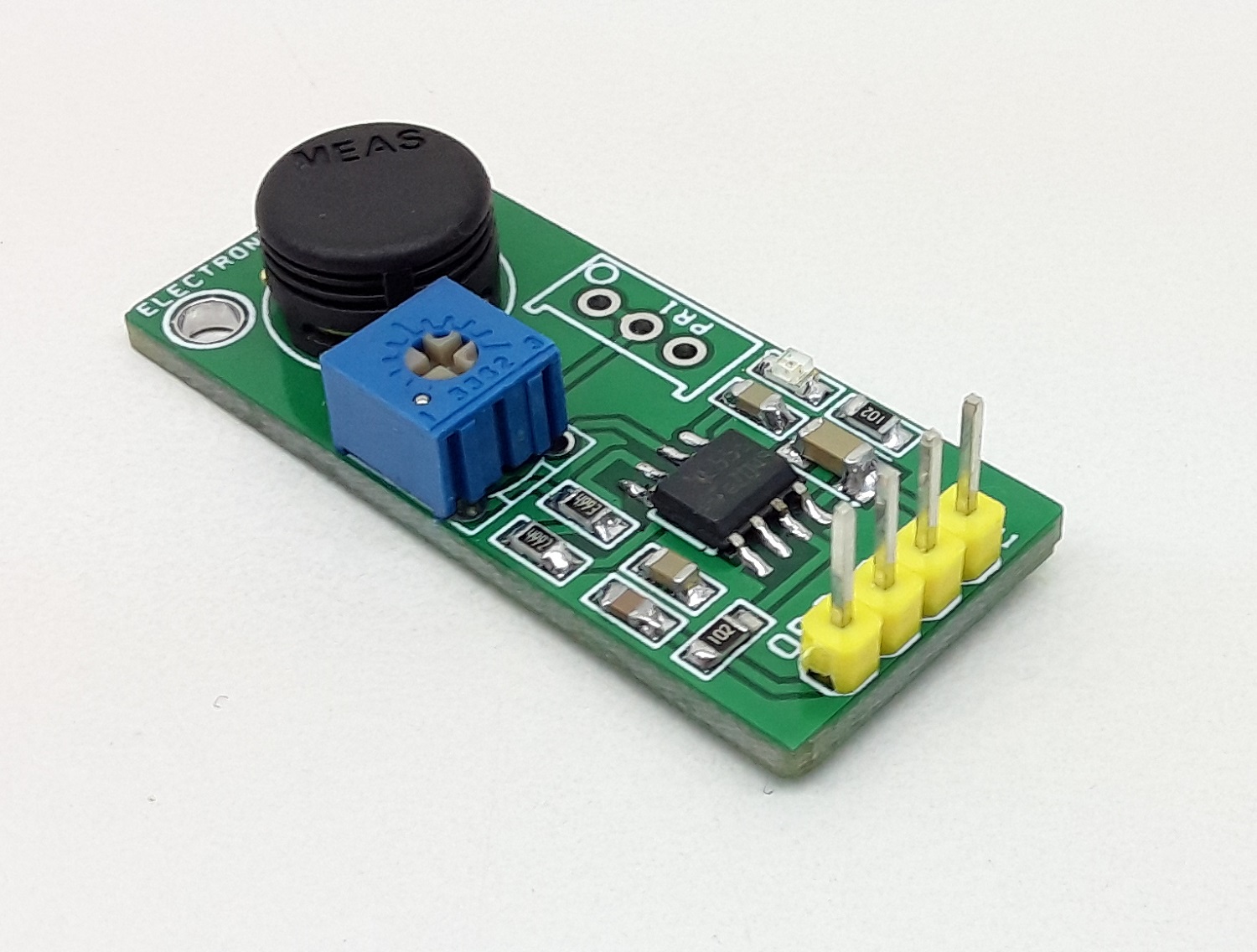
This sensor board provides frequency output as per relative humidity value. The project is based on a unique capacitive cell, this relative humidity sensor is designed for high volume, cost-sensitive applications such as office automation, automotive cabin air control, home appliances, and industrial process control systems. It is also useful in all applications where humidity compensation is needed. The circuit is built using a low-cost NE555 timer as an astable generator, humidity sensor MK1 acts as a variable capacitor and is connected to the TRIG and THRES pin. Pin 7 is used as a short circuit pin for resistor R3. The HS1101LF equivalent capacitor is charged through R2, R3, and PR1 is set the threshold voltage (approximately 0.67Vcc) and discharged through R2 only to the trigger level (approximately 0.33Vcc) since R3 is shortened to the ground by pin 7. Since the charge and discharge of the sensor run through two different resistors, R2 and R3, the duty cycle is determined by the following formulas.
Humidity Sensor – Humidity to Frequency Output – [Link]


