Pixblasters Video LED Controller transform LED strips to huge displays
Combine LED strips to create a huge display that acts as a regular video monitor. All this with the FPGA based RGB LED controller that is capable of controlling up to 16,384 WS2812 based RGB LEDs at 60 FPS.
Combine LED strips to create a huge display that acts as a regular video monitor. All this with the FPGA based RGB LED controller that is capable of controlling up to 16,384 WS2812 based RGB LEDs at 60 FPS. Not only that, but you can daisy chain multiple controllers which can control up to hundreds of thousands of LEDs.
Due to their high cost and complexity, huge, shiny, beautiful video displays with thousands of LEDs have always been out of reach of enthusiasts and small business owners. Pixblasters MS1 changes all of that.
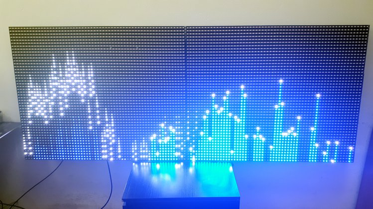
Pixblasters MS1 enables DIY enthusiasts and signage professionals, even those with minimal technical skills, to turn a bunch of addressable RGB LED strips into immense video LED displays. This FPGA-based LED controller enables new levels of professional-grade digital signage that cannot be attained by standard LED modules. The LED strips can be curved and glued to different surfaces to form giant yet economically viable video installations that can span entire buildings.
Key Features
- Easy to use with any computer, any OS:
Pixblasters connects to any computer as an ordinary external monitor, with no programming needed. You can use it with Raspberry Pi, PC, media boxes, phones, etc. Simply plug in the monitor cable and the controller will smoothly drive the LEDs at the maximum frame-rate of 60 fps. - Straightforward display content and management:
Anything that shows in the selected part of monitor image shows on the LEDs as well. No need for special software for anti-aliasing or fonts. Use any digital signage software and add layered screen divisions, text, animations, video, RSS… LEDs work at their maximum speed and are perfectly synchronized, no matter the number of LEDs and chained MS1 controllers, or the display size. - Display size and resolution:
A single MS1 can control 4.7/17.7 m² (~ 50.6/190.5 ft²) while daisy-chained MS1s can control an LED display of hundreds of square meters using thirty to sixty LED strips. Daisy-chained controllers that drive a total of 16,384 LEDs can support HD LED displays. - Remote controllable and customizable:
Control it remotely from anywhere in the world through the network interfaces of the driving computer. Don’t worry about the LED display’s architecture. Users with special display applications (such as big, real-time timetables and scoreboards) can develop custom software for a computer monitor. - Open source FPGA demo:
Use the hardware platform for experimenting with, and learning about, driving RGB LEDs. Note: the open source FPGA demo design supports a subset of the fully-featured Pixblasters MS1 LED controller.
Features
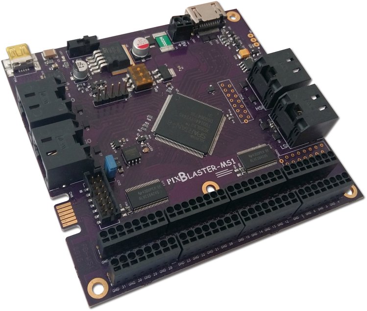
- Xilinx® Spartan®-6 XC6LX9-3 FPGA chip
- On-board Microchip PIC18F26J50 microcontroller:
- The microcontroller connects to the PC, runs the configuration software, and permanently stores the configuration data. It also enables simple firmware updates with any new features.
- Output resolutions (H x V): 512 x 32 (native), 256 x 64, 128 x 128, 180 x 96, etc.
- Board dimensions: 95 x 100 mm
- LED details:
- 32 LED digital outputs: up to max. 512 LEDs per output
- Maximum WS2812B/SK6812 LED display frame rate: 60 fps
- Currently supported LED types: WS2811, WS2812, WS2812B, SK6812
- Supports RGB666 (256K colors) color format
- Maximum driving capacity of the single MS1 controller is 16,384 RGB LEDs
- 5 VDC 24 mA digital outputs compatible with the most popular RGB LED types
- Connectivity:
- HDMI video input allows for easy connection from the computer – it also works with adapter cables should your computer have a DVI® output
- Push-in strip power and signal connectors enable easy wiring without soldering
- Validated with different computers and different OS’s: Raspberry Pi Linux, Microsoft® Windows® PC, media boxes, phones and tablets…
- On-board EDID flash enables automatic connection to any computer and any OS
- Power:
- Protected 5 VDC power supply input
- The LED power supplies need to be wired separately to fulfill the power and current requirements of giant LED displays
- Display controls:
- Cropping image window
- Display formatting
- LED timing parameters
- Supports different video resolutions (max. 720p – 1280 x 720 at 60 fps)
- Integrated video input cropping and mirroring
- Multiple lines per output mode
- LED gamma correction
- Daisy-chain multiple controllers:
- Each MS1 board can work either as the Master or the Slave video controller
- Daisy-chained controllers can drive more than 200,000 perfectly synchronized LEDs differently arranged in HD LED displays
- The high-speed video link between MS1 boards assures max. fps and synchronicity
- Low-speed control link interface
- Video and control links use common UTP cables (Ethernet)
- On-board DIP switches allow for an easy selection of the Master, Slave and six other FPGA configurations, including user-defined FPGA configurations
- A single digital output has the ability drive multiple output video horizontal lines
- Configuration is fully customizable through a menu on the PC connected via the USB serial cable
The project is live on Crowd Supply and basic pledge for Pixblasters Go costs $219.


“One should note that the article is about WS2811’s; but, the first photo is of Adafruit’s Neopixels, which are WS2812.nnThis is significant because WS2811’s are driven by 12VDC, and have a data input of 0 and 12VDC. Whereas, WS2812’s are driven by 5VDC.
the first photo is of Adafruit’s Neopixels, which are WS2812.nnThis is significant because WS2811’s are driven by 12VDC, and have a data input of 0 and 12VDC.
Supports different video resolutions 720p – 1280 x 720 at 60 fps
it is so cool