Use an ATtiny85 to Build Your Own Electronic Compass
At the very heart of any embedded electronics system is a microcontroller. While the ATtiny series of microcontrollers have been around for a while now, they recently started getting noticed on a very high scale as DIYers and professional designers now use them in various projects which ordinarily would have featured a much bigger MCU or an Arduino.
At the very heart of any embedded electronics system is a microcontroller. While the ATtiny series of microcontrollers have been around for a while now, they recently started getting noticed on a very high scale as DIYers and professional designers now use them in various projects which ordinarily would have featured a much bigger MCU or an Arduino. The ATtiny85 microchip is a small, affordable, and very versatile 8-bit AVR RISC-based microcontroller that features an 8KB programmable flash memory, 512 Bytes of SRAM, 512B EEPROM, 6 general-purpose I/O lines, 4 channel 10-bit A/D converter, internal and external interrupts and more.
Compared with the microcontrollers like the atmega328p, the Attiny85 has a smaller form factor, which makes them perfect for projects with small overall size requirements, like the electronics compass designed by Instructables user; Rahul7321, for the Instructables Maps challenge.

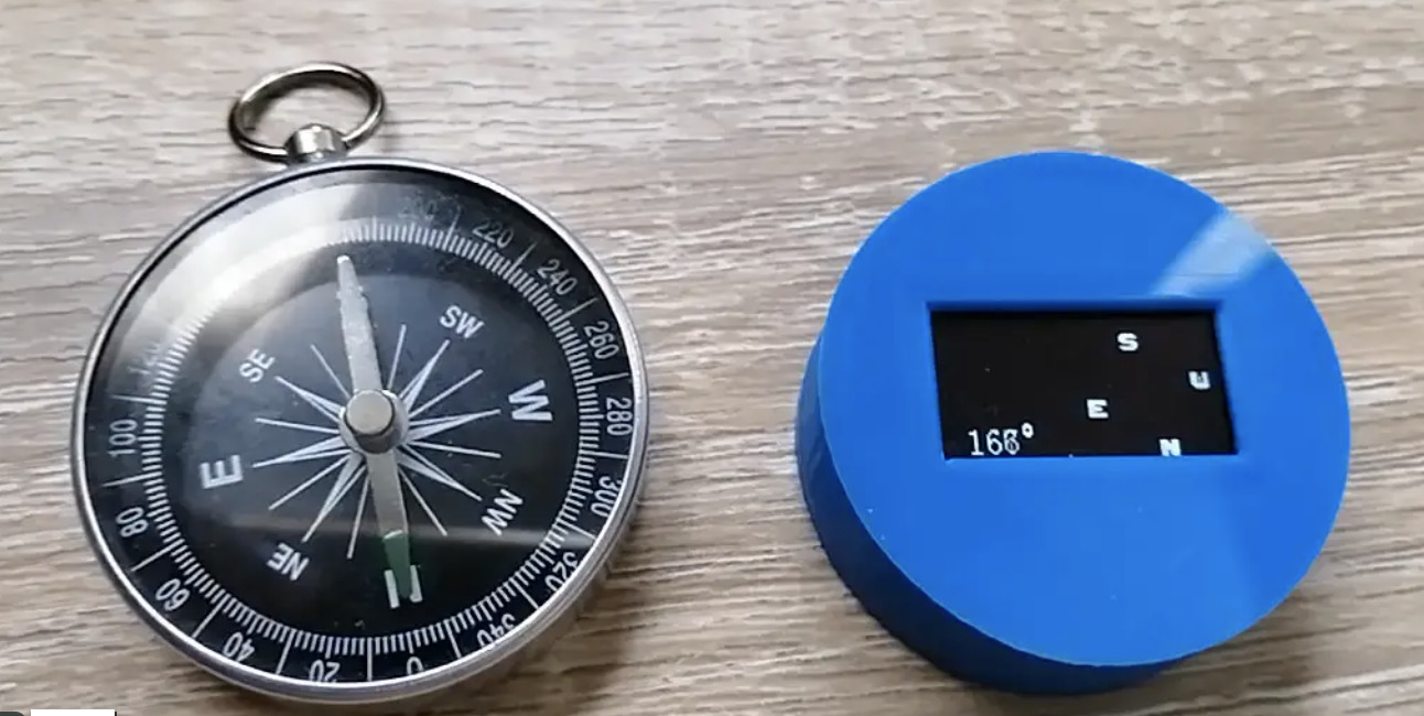
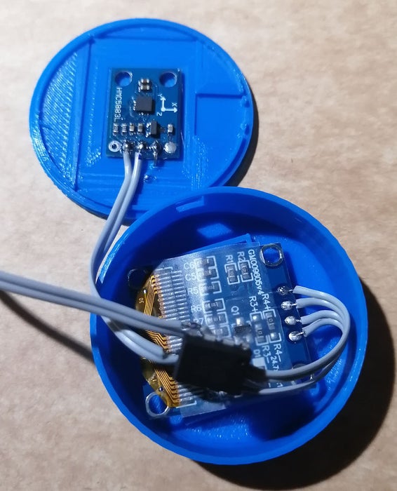
The tiny compass, which was built around the size of a typical analog pocket compass, comprises of an HMC5883L magnetometer, an OLED display, and the ATtiny85 microcontroller, all connected via the I2C to reduce wiring complexities. The HMC5883L magnetometer is used to sense the Earth’s magnetic field and the data obtained is processed by the Attiny85 and displayed on the tiny OLED in a manner similar to that of the analog compass.
Describing the project and the choice of the ATtiny85 microcontroller, Raul mentioned that the major challenge for the project was to maintain a small form factor, but using the ATtiny85 microcontroller which has just 8kb of programmable flash memory also meant they needed to reduce the size of the firmware. This was achieved by leveraging the I2C protocol in such a way that, it not only reduces the physical form factor but also helps keep a small code footprint.
A more detailed list of components used in the development of the project, asides from the ATtiny85 is provided below;
- An HMC5883L Magnetometer
- 3.7V 300mAh LiPo battery
- A self-locking square button switch
- 2 parts of a 3D printed case
- A 0.96” SSD1306 128 x 64 I2C OLED display
- 2x PCB of dimensions 17mm x 10 mm and 13mm x 18 mm), and
- A micro USB 5V 1A Lithium battery charger.
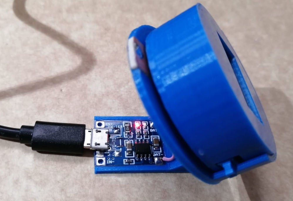
One additional cool feature of this project which you might find handy for any other project you design is the charging mechanism, which is implemented in such a way that the user need only place the device on a platform to charge it.
The project is completely open-source and all information you might need to build your own, from schematics to firmware and a step-by-step build guide are all available on the project’s instructable page.


