Dintervalometer, A Custom Made Intervalometer For DSLR Cameras
If you want to take a timelapse with your camera, it may be helpful to use an intervalometer. It is an attachment or facility on a camera that operates the shutter regularly at set intervals over a period, in order to take timelapse series or take pictures after a set delay.
If you want to take a timelapse with your camera, it may be helpful to use an intervalometer. It is an attachment or facility on a camera that operates the shutter regularly at set intervals over a period, in order to take timelapse series or take pictures after a set delay.
Daniel Knezevic had developed a custom made intervalometer for DSLR cameras. Dintervalometer (Deni’s intervalometer) enables cameras to shoot time lapses and allows shutter speeds longer than the 30s.
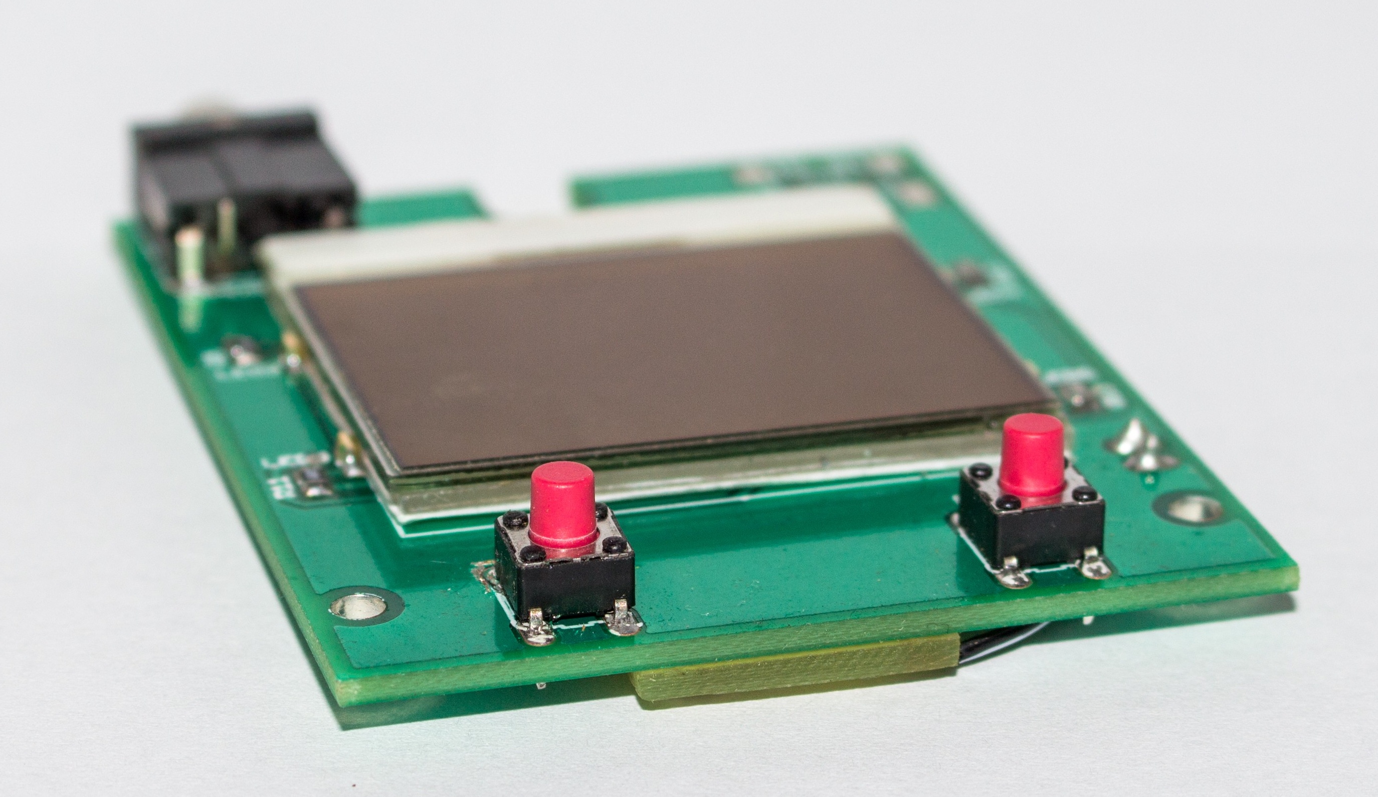
The Dintervalometer is built with an Atmega328P clocked at 10MHz, a PCD8544 84×48 pixel monochrome LCD display with a backlight, a 3.5mm male jack connector, and two tactile push buttons all combined together on a small PCB.
Dintervalometer Features
- Intervalometer: It is used for time-lapse photography. It controls how often, how long and how many shots are taken.
- Bulb mode: It allows to take time exposures longer than 30s.
- Backlight
- Charging via USB
The Display & Backlight
The PCD8544 LCD display can be powered using 3V3 and it draws very small amounts of power (around 200uA) making it extremely good for use in battery powered devices. It is typically used in Nokia 5110/3310 phones, and it interfaces to microcontrollers through a serial bus interface (SPI).
A custom made backlight were designed to allow using the Dintervalometer in the dark without an additional lamp. It operates like a backlight of a cell phone: it is active for 10 seconds when the user presses a button or the Dintervalometer finishes some job.
The backlight consists of these materials:
- A sheet of white paper
- A piece of transparent plastic
- A double-sided tape
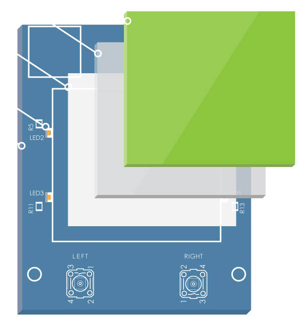
The first layer of the backlight is a sheet of white paper. Its main function is to reflect the light of the LEDs. Then it comes the piece of transparent plastic. The top of the plastic is sanded with a fine sandpaper to diffuse the light. Finally, the LCD comes on the top. The layers are glued together with a double-sided tape.
Powering & Charging
Dintervalometer’s circuit is powered using a LiPo battery and a very low drop 3V3 voltage regulator (TPS79933). A MAX1555 Li+ battery charger IC is used to charge the battery, which also can be powered via USB.
To prevent the over-discharge of the LiPo battery, Dintervalometer monitors and measures the battery voltage every 60 seconds. The user can always see the current status of the battery on the LCD. When the battery reaches the critical voltage, a “Low battery” notification will be shown, then the device will turn off.
The voltage measuring process is done using a voltage divider and AVRs internal 1V1 voltage reference.
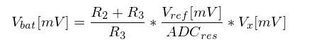
The following equation is used to measure the battery voltage in mV, with the known values R2=10k, R3=3k3, Vref=1100mV, ADCres=1024.
Controlling The Camera
Using the 3.5mm male jack connector, the Dintervalometer will trigger the camera to focus and to take a picture. The jack consists of three wires: ground, focus and shutter.
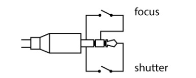
To focus the camera, the focus wire has to be connected to the ground. To release the camera both wires have to be connected to the ground. Dintervalometer is tested with Canon EOS 700D. It has a jack plug for remote shuttering.
The Software
The software is written in C and compiled with avr-gcc. It is divided into 6 logical modules:
- TIMER: Initializes Timer1 and provides an interrupt based delay function.
- BATTERY: Initializes ADC to read the battery voltage.
- BACKLIGHT: Functions are used to control the backlight (initialize and update).
- GPIO: Initializes IO ports for buttons, camera output, battery charger status indication, auto cut off control output.
- LCD: It represents the pcd8544 LCD driver, it is reusable code for other projects. The driver provides the API to initialize, control, and print text on the LCD.
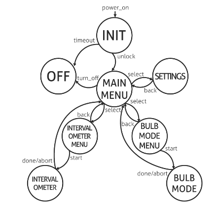
- STATE: The state machine is implemented by using function pointers. Each menu state has three basic operations; show data on LCD, wait for user input, update backlight and battery status, and handle button presses/holds.
Dintervalometer Sources
This project is published on hackady.io. Daniel had shared all the source designs and scripts online, so you can get it on its Github repository.


