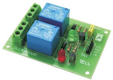
Dual Relay Driver Board
Description Dual Channel Relay Board is a simple and convenient way to interface 2 relays for switching application in your project. Input - 12 VDC @ 84 mA Output - two SPDT relay Relay specification - 5 A @ 230 VAC Trigger level - 2 ~ 5 VDC Berg pins for connecting power and trigger voltage LED on each channel indicates relay status Power Battery Terminal (PBT) for easy relay output connection Four mounting holes of 3.2 mm each PCB dimensions 49 mm x 68 mm Schematic Parts List
Description
Dual Channel Relay Board is a simple and convenient way to interface 2 relays for switching application in your project.
- Input – 12 VDC @ 84 mA
- Output – two SPDT relay
- Relay specification – 5 A @ 230 VAC
- Trigger level – 2 ~ 5 VDC
- Berg pins for connecting power and trigger voltage
- LED on each channel indicates relay status
- Power Battery Terminal (PBT) for easy relay output connection
- Four mounting holes of 3.2 mm each
- PCB dimensions 49 mm x 68 mm
Schematic
Parts List
Hello!
Thank you for sharing the schematics and even the list of parts to buy. I’m not a pro with electronics, and I’d like to ask if you could add the different components one would need to use a 5V supply (of course, with 5V relays). I’m working with Arduino and I intend to build a 2 channel 5V relay board to control a garage motor and another security system.
Once again, thank you for everything you’ve already shared!