A signal generator is an electronic device that generates electronic signals and waveforms. These electronic signals are either repeating or non-repeating as per the requirements and field of applications.
Asignal generator is an electronic device that generates electronic signals and waveforms. These electronic signals are either repeating or non-repeating as per the requirements and field of applications. It is generally used in designing, testing, troubleshooting and repairing electronic devices. A signal generator can generate various kinds of waveforms. Most common are the sine wave, square wave, sawtooth wave and triangular wave.
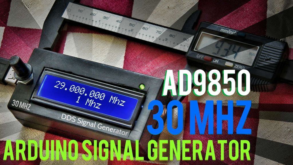
This instructable shows a full guide on how to make a 30 MHz signal generator for 12$, using an Arduino and an AD9850 DDS synthesizer module. The circuit is pretty simple and small enough to fit in your pocket. Kedar Nimbalkar, the author of the instructable, says:
A precession signal generator is very easy and affordable to make using an Arduino and DDS synthesizer (ad9850) . It’s World’s first smallest portable signal generator.
You can make decent 0 -30 MHZ frequency Signal generator only in 12$ .
30 MHz signal generator using Arduino
Parts List:
1. Arduino Pro mini
2.AD9850 (DDS Synthesizer)
3.16×2 LCD Display ( Hitachi HD 44780 )
4.Rotary Encoder
5. CP2102 (or any USB to serial converter)
I think you are familiar with all of the above items except the AD9850 (DDS Synthesizer). First of all, you need to know what does DDS stand for.
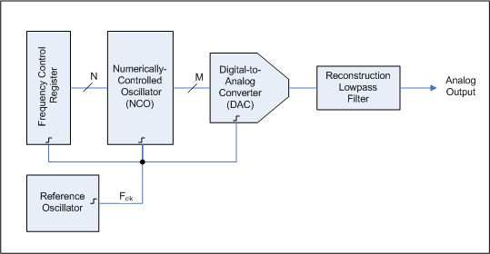
Direct Digital Synthesizer Block Diagram
Direct digital synthesizer (DDS) is a type of frequency synthesizer used for creating arbitrary waveforms from a single, fixed-frequency reference clock. A basic Direct Digital Synthesizer consists of a frequency reference, a numerically controlled oscillator (NCO) and a digital-to-analog converter (DAC).
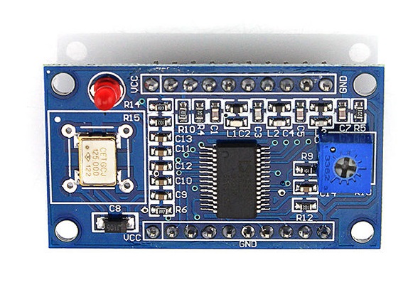
AD9850 (DDS Synthesizer):
The AD9850 is a highly integrated device that uses advanced DDS technology coupled with an internal high-speed, high-performance D/A converter and comparator to form a digitally programmable frequency synthesizer and clock generator function. When referenced to an accurate clock source, the AD9850 generates a spectrally pure, analog output sine wave. In a nutshell, AD9850 works on DDS (direct digital synthesis ) which can generate analog waveforms with digital input.
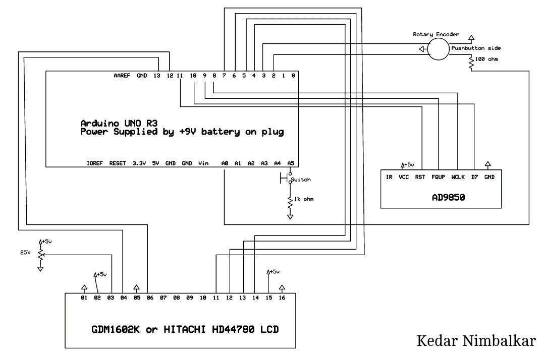
The circuit diagram is very simple. You can make it on a breadboard, or just solder components end to end to make it more compact.
Arduino Based Signal Generator Circuit Diagram
The Arduino sends digital signals to AD9850 and the module generates analog output Sine wave. The display, which is connected to Arduino, shows output frequency and step increment/decrement value. The rotary encoder is for changing frequency. Though the AD9850 module can generate up to 40 MHz frequency, but after 30 MHz the output frequency becomes unstable. So in this circuit, the maximum frequency is limited to 30 MHz.
You can make a decent 0-30 MHz frequency signal generator for only 12$ . If you are pro “overclocker”, then 40 MHz in same price .
The signal generator runs on 5 Volt power supply and current should not exceed 270mA.