Constant-on-time buck-boost regulator converts a positive input to a negative output
This is a LM5010 buck-boost regulator able to convert a positive input ranging from 10-50Vdc to -12V output. by Robert Bell @ www.edn.com Buck regulators find wide application as step-down regulators for converting large positive input voltages into a smaller positive output voltages.
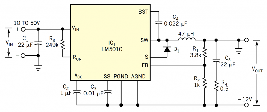
This is a LM5010 buck-boost regulator able to convert a positive input ranging from 10-50Vdc to -12V output. by Robert Bell @ www.edn.com
Buck regulators find wide application as step-down regulators for converting large positive input voltages into a smaller positive output voltages. Figure 1 shows a simplified buck regulator that operates in continuous-conduction mode—that is, the inductor current always remains positive. The output voltage, VOUT, is equal to D×VIN, where D is the duty-cycle ratio of the buck switch, Q1, and VIN is the input voltage. The duty cycle, D, is equal to TON/TS, where TON is the on-time of Q1 and TS is the switching-frequency period.
Figure 3 shows a low-cost buck-boost converter based on the LM5010 buck-regulator IC that converts a 10 to 50V positive supply voltage into –12V. Although many applications use a fixed switching frequency and modulate the output pulse width, this design features a constant-on-time approach in which the IC’s internal output transistor turns on for an interval that’s inversely proportional to the difference between the circuit’s input and output voltage.