Switch debounce circuit uses only one gate
The circuit in Figure 1 produces a single debounced pulse each time you press S1. Moreover, the circuit uses only logic power from the remote pull-up resistor, R2.
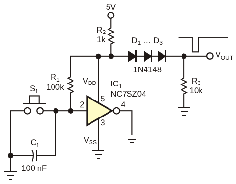
The circuit in Figure 1 produces a single debounced pulse each time you press S1. Moreover, the circuit uses only logic power from the remote pull-up resistor, R2. You can use the circuit to detect when a key is pressed in a non-energized device, such as a device in a system that’s just coming up from standby.
The circuit operates as follows: Assume that you have not yet pressed S1 and that C1 is in a charged state. Under these conditions, R1 drives IC1 toward VSS (ground), causing the IC to consume virtually no power. This action allows VOUT to remain near 5 V. However, when you press S1, C1 rapidly discharges and drives IC1 toward VDD. Under these circumstances, IC1 conducts heavily, pulling VOUT near 0 V until R1 charges C1 enough to again drive IC1 toward VSS. Once C1 charges sufficiently, IC1 goes to VSS and stops drawing power. This action unloads VDD and causes VOUT to return to a high state. D1 to D3, in conjunction with R3, shifts the level of VOUT for improved compatibility with CMOS logic.
[source: https://www.edn.com/switch-debouncer-uses-only-one-gate/]

