AC Inductance and Inductive Reactance
Introduction In the previous tutorial concerning AC resistance, we have seen that the behavior of a resistor is the same in DC or AC regime under normal frequencies. However, other basic electrical components such the inductor, strongly depends on the frequency of the AC signal.
Introduction
In the previous tutorial concerning AC resistance, we have seen that the behavior of a resistor is the same in DC or AC regime under normal frequencies. However, other basic electrical components such the inductor, strongly depends on the frequency of the AC signal.
A presentation of the concept of inductance is given in a first section in order to understand the phenomena that dictates how inductor works. A description of inductors is also given later in this same section. We explain as well why certain type of inductors are better suited for high frequency applications.
A second section highlights the dependence with the frequency of the inductance and phase shift observed in them.
Finally, a last section deals with the association of resistor and inductor in order to create filtering circuits.
Presentation
The Inductance
The inductance, is a property of an electrical component that consists of creating an opposition to the variation of the current when an alternating voltage is applied to its terminals. This moderation of the current can be explained by the electromagnetic law of induction that has been detailed in the tutorial about AC resistance.
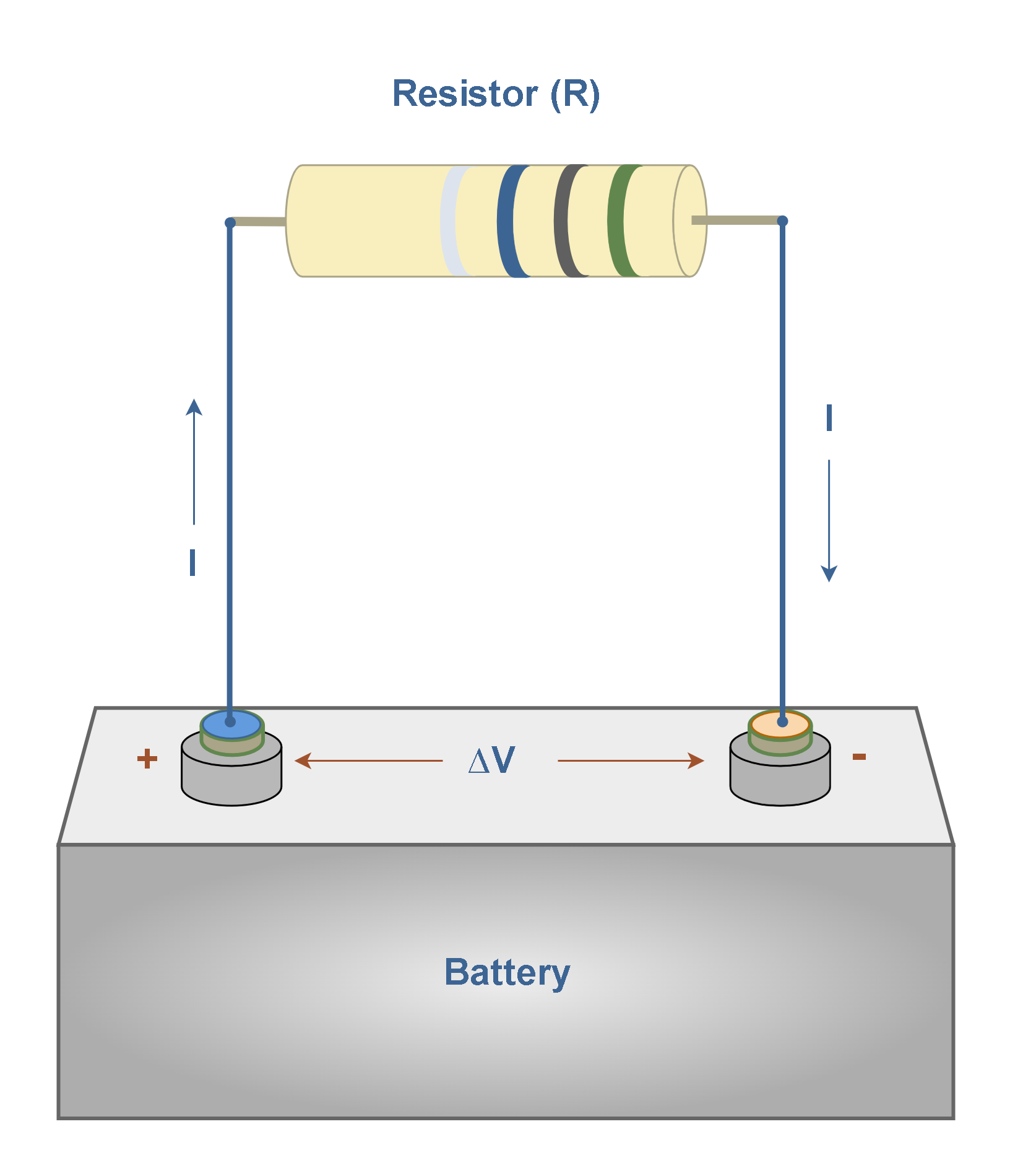
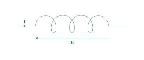
In order to understand this definition better, let’s consider a circuit that consists of an AC source and no other components other than a conductive wire of length l shorting the source as shown in Figure 1 below :

The current loop formed by the circuit creates a magnetic field B when a current I, generated by an AC source, flows into it. The circle with a cross denotes that when the current I flows as drawn in Figure 1, the magnetic field is directed downwards.
According to Lenz’s law, if the current is of AC form, B is as well alternating, which creates an induced current Ii, generated by an electromotive force E, in order to moderate the variation of the magnetic field with an induced field Bi. When the current Ii flows as shown in Figure 1, the induced magnetic field is directed upwards, which is specified by the circle with a dot.
The expression of the magnetic field B is given by the following Equation 1 :
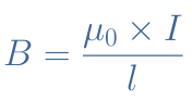
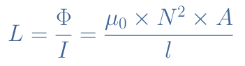
Where μ0=4π×10-7 H/m is the magnetic permeability of vacuum. The magnetic flux is therefore given by Φ=B×A with A being the cross-section of the wire loop. Finally, the inductance L is given by the Equation 2 below :
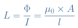
The inductance does therefore only depend on the geometry and not the source (voltage or current) and it is expressed in Henry (H). In order to understand better what this quantity represents, it is worth giving the expression of the electromotive force E in Equation 3 :
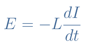
If we isolate L in this equation, we understand that 1 Henry represents the inductance of a circuit in which an electromotive force of 1 Volt is induced when a current alternating at a rate of 1 Amp per second is flowing into it.
Inductors
In order to considerably increase the inductance of a wire, it would be very constraining to only work on the geometrical parameters A and l. In practice, inductance components are called inductors which are wires with a certain number of turns around an axis and represented as an electrical component such as shown in Figure 2 :
If we consider a number N of windings, Equation 2 becomes modified to Equation 4 :
A winded wire with N turns can therefore see its inductance increased by a factor N2 in comparison with the same wire presented in Figure 1.
There is another modification that can be done with inductors to increase their inductance : add a core. The core represents the central region of the inductor, surrounded by the wire.
It can be made of a non-magnetic material such as plastic, ceramic or even air which is similar to vacuum in terms of magnetic properties. These type of inductors are known as air-core inductors and represented symbolically such as in Figure 2, they have a lower inductance but a better frequency behavior.
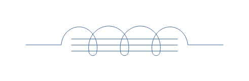
The other type are ferromagnetic-core inductors, their core is made from a magnetic material that increases the total magnetic permeability. Ferromagnetic-core inductors have a much higher inductance than air-core inductors because they can concentrate better the magnetic field. However, they are less suited for high frequency applications because of the important presence of Eddy currents in the core when the frequency increases, leading to losses by heat.
Ferromagnetic-core inductors can be represented such as shown below :
Frequency behavior
Reactance
It is quite ambiguous to speak about an “AC inductance” since the concept of inductance is only valid in AC regime. Indeed, considering the Equation 3 and what has been said in the previous section, one can understand that the electromotive force, the induced current and magnetic field are only existing in the presence of an AC source. As a matter of fact, in DC regime, an inductor is simply considered as a simple wire shortening a part of the circuit.
The impedance of an inductor can be defined as the opposition to the current that an inductive component generates. Impedances, such as explained during another tutorial, are complex numbers which have a real part representing a resistance and an imaginary part representing a reactance.
For an inductor, the reactance XL represents the opposition of the component to a change of current. The impedance of an inductor is a pure imaginary number, meaning that no resistance is considered and its reactance is given in the following formula :
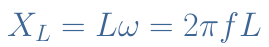
The opposition to an AC current increases therefore linearly with the frequency. At f=0 Hz (DC regime), the inductor as previously said act as a short circuit and when f→+∞, it acts as an open circuit.
Phase shift
The impedance of the inductor is simply given by ZL=jXL. The phase shift φ between the current across the inductor and the voltage generated at its terminals (electromotive force) is constant and given by Arg(ZL)=arctan(y) with y→+∞, which gives φ=+π/2 rad or 90°.
This particular value of phase shift, as emphasized in the tutorial about phase splitters, is called a quadrature phase advance and illustrated in Figure 3 :
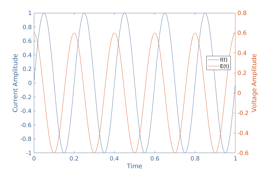
If the amplitude (reference to peak) of the current is given by Imax, the amplitude of the electromotive force is Vmax=Imax×XL.
Induction phenomena
When the AC source frequency increases, similar phenomena that have already been described in detail in the AC resistance tutorial take place inside inductors.
The first one is the skin effect, it is caused by a redistribution of the current near the border of the wire constituting the inductor. This high concentration of the current in a small region increases the resistance of the inductor, which as a consequence, lead to heat losses.
The proximity effect is also very present in inductors. Indeed, each turn of wire induces Eddy currents in the border region of their neighbors wires. Such as for the skin effect, this tends to reduce the effective cross-section for the current which increases the resistance.
RL filters
We have seen with this tutorial that inductors are very sensitive to the frequency but on the other hand, resistors are not. So the natural question that comes is what happens if we combine these components in a same circuit ?
Let’s therefore consider a RL circuit which input voltage is noted Vin and output voltage Vout :
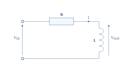
We call TV the transfer function of the circuit which is defined by the ratio Vout/Vin. In order to find the expression of TV, we can simply look at the circuit as a voltage divider. As a consequence, we have :
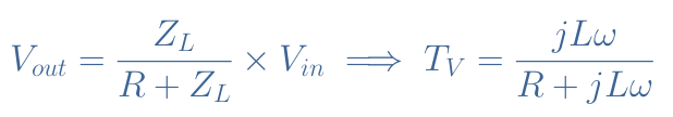
This function is interesting because it gives us simultaneously the voltage gain and phase shift of the circuit for any frequency.
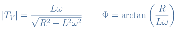
The gain is given by the module of TV and the phase shift Φ by its argument, both are given in Equation 7 below. We recommend to the reader to refer to the tutorial about complex numbers in order to know how to determine the module and argument of a complex fraction.
Let’s take R=1 kΩ and L=100 mH and plot the two quantities presented in Equation 7 in logarithmic scale for the frequency. The resulting plot is commonly known as a Bode diagram and shown in Figure 5 :
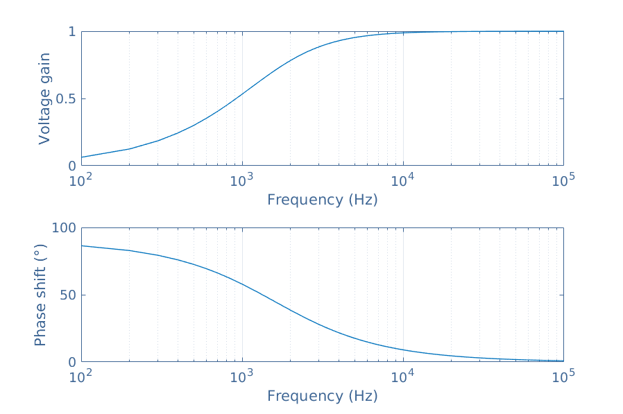
At low frequency (DC regime) the inductance impedance is negligible, therefore the voltage drop is completely absorbed by the resistance and none in the inductance. A quadrature phase shift is observed in DC regime.
At high frequency, the inductance impedance prevails and the voltage drop is therefore absorbed by the inductance which gives a gain that tends to 1. The phase shift tends to zero as the frequency increases.
As a conclusion, we can say that an RL circuit acts as a high pass filter since the low frequencies are not transmitted.
Conclusion
It as been shown during this tutorial that inductors behave differently than resistor with change of frequency.
First of all, a presentation of the concept of inductance has been given. The inductance is an important factor to understand the induction law, it describes how strong a component will react with a change of the current within a circuit. Later, through the presentation of inductors, we have seen that the inductance can be increased with windings and with the presence of a magnetic core.
In a second section, we looked more closely to the frequency behavior of inductors. Their impedance increases linearly with the frequency, in DC regime they behave as short circuits and become open circuits when the frequency is very high.
Combining inductors with resistors has been investigated in a last section. We have shown how to describe the behavior of a RL filter with the concept of transfer function and Bode diagram.