


Over the years FPGAs have become readily available to the maker community. They are now more accessible than ever as many development boards has seen the light. It’s now possible to embed a soft-core MCU into an FPGA rather than using a hard-core ASIC MCU and here is where PulseRain comes into play with an open source design down to the silicon level.
The PulseRain M10 board embeds an open source soft MCU core (96 MHz) in an Intel/Altera MAX10 FPGA, while is Arduino compatible. In addition, the soft-core MCU features onboard resources like voice CODEC, microSD socket, SRAM, on-chip ADC, and dual IO voltages. The board will soon be available for funding on crowdsupply.com.
Features & Specifications
- FPGA: Intel/Altera 10M08SAE144C8G
- Logic Elements: 8 K
- Block Memory: 378 Kb
- User Flash Memory: 32 KB
- 18 x 18 Multipliers: 24
- Internal Configuration: 2 (This FPGA does not need external memory for configuration)
- PLLs: 1
- On-chip A/D Converter: 12 bit
- Temperature Sensor: On-chip TSD (Temperature Sensor Diode)
- Package: 144-pin EQFP
- Microcontroller: Soft-core FP51-1T, with support package for Arduino IDE
- Clock Rate: 96 MHz
- Processor Core: Enhanced 1T 8051, with RISC implementation
- Throughput: Single clock cycle execution for most instructions
- Instruction Memory: 32 KB
- Data Memory: 8 KB
- On-chip Debugger: Yes (supports code download throughput of 921600 bps)
- Open Source Compiler: SDCC (Small Device C Compiler)
- Onboard Peripherals and Components:
- Voice CODEC: Silicon Lab Si3000, with onboard microphone and speaker jack
- DTMF Decoder: Available through software library
- UART/PWM/I2C: The default configuration has 2 UARTs, 6 PWMs and 1 I2C
- SRAM: 1 Mbit serial SRAM (Microchip 23LC1024)
- microSD Socket: Molex 472192001
- OpAmp and Potentiometer for Analog Input: 6 analog input channel, 1 potentiometer on A0
- USB: USB/UART bridge (FT232R), with 921600 bps throughput
- JTAG Header: Yes
- Push Button: 2
- Oscillator: 12 MHz crystal oscillator, with DIP package
- LEDs: 6 (2 for USB/UART indication, 1 for IO power, 3 for general purpose)
- Form Factor and Input/Outputs:
- Arduino UNO Rev 3 Compatible Dimension: 2.1 inch x 3.2 inch
- Maximum Height: 0.5 inch
- IO Pin Map: Compatible with Arduino UNO Rev 3
- IO Voltage: Dual voltage support (3.3 V / 5 V)
- Power: 5 V USB or 7-12 VDC jack
- Host Interface: microUSB
Please follow and like us:
RELATED POSTS
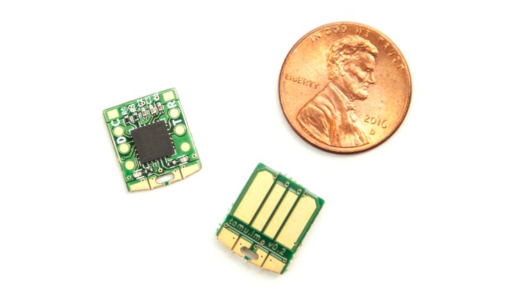 13 December, 2017 Tomu – An ARM board which fits inside your USB connector
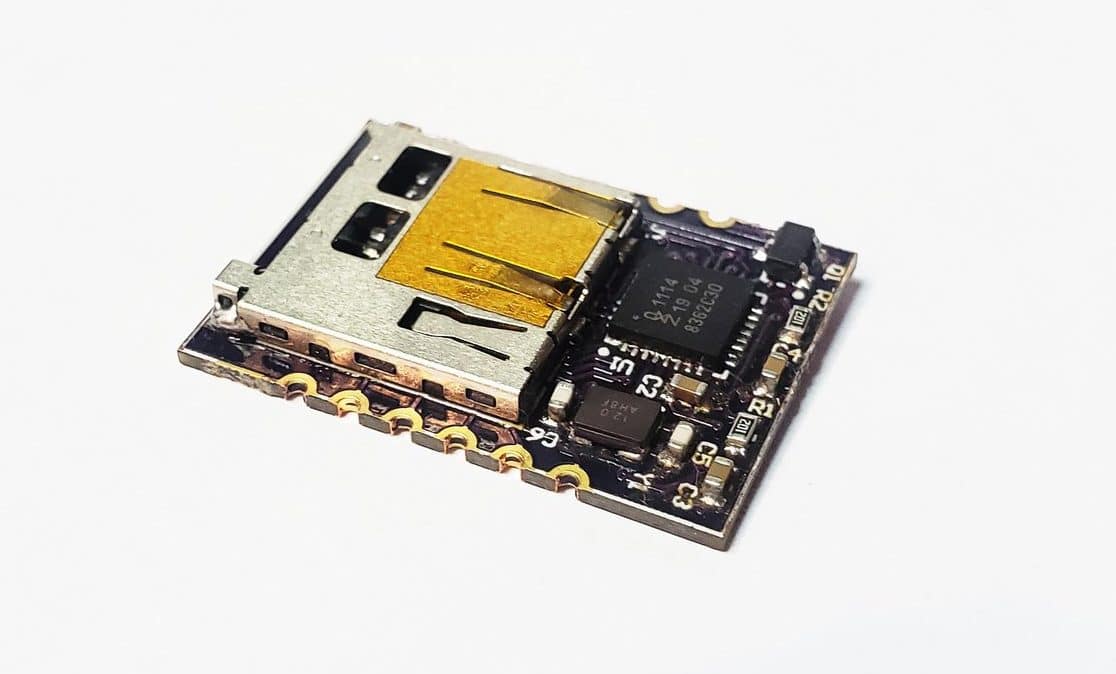 4 October, 2021 MEET WAVE III – A PORTABLE 2-CHANNEL STEREO AUDIO PLAYER MODULE
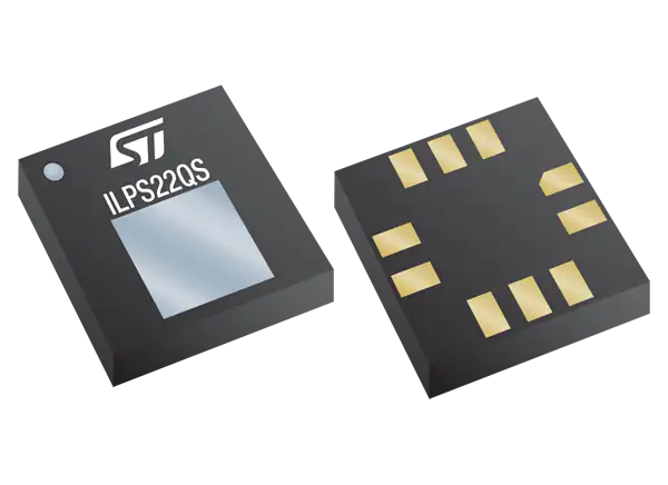 19 January, 2022 Dual full-scale, absolute digital output barometer with embedded Qvar electrostatic sensor
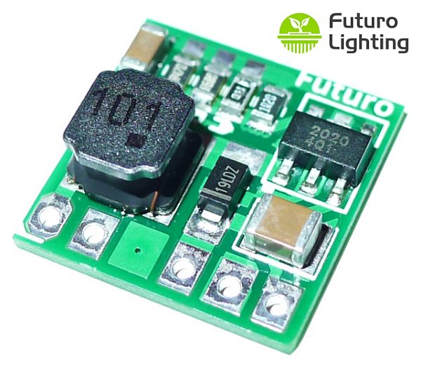 23 July, 2015 A low-cost 0.5A 33V LED driver module with 90+% efficiency
 12 October, 2020 Micro Peltier modules have footprint down to 3.4mm square
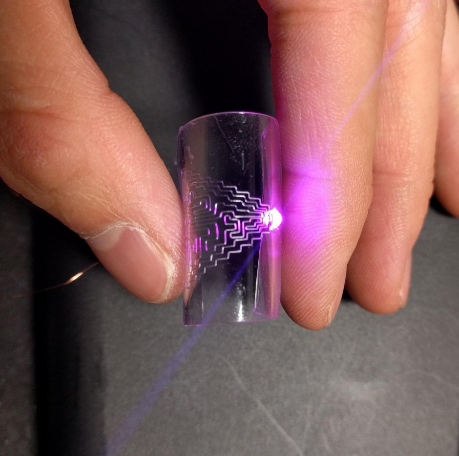 8 January, 2018 Researchers Develop New Technique To Print Flexible Self-healing Circuits For Wearable Devices


Such wasted I/O. The FPGA has 101 I/Os and it gives us just a dozen?
To be fair, a lot of those 101 I/O pins are actually dual purpose, such as for JTAG and CONFIG. When it comes to the M10 board, some of them have to be used for analog as well. The pin assignment for M10 is as following:
CODEC 6
SRAM 6
microSD 6
Arduino IO 16
JTAG IO 3
Push Button 2
FT232R 5
Vref 8
Analog In 8
Clk In 4
Config 5
LED 3
JTAG 4
Unassigned 25
As you can see, most pins are already occupied by other functions, or used for peripherals. Only 25 out of the 101 I/Os are unassigned.
FPGA and CPLD’s are dead-end if you’re looking for open development options.