


Renesas Synergy™ TB-S5D3 Target Board Kit helps designers evaluate the operation and performance of the S5D3 Microcontrollers. The S5D3 Target Board Kit offers initial firmware development and evaluation of the Synergy Software Package (SSP) on the Synergy™ S5D3 Microcontrollers. The Kit connects via a USB connector for the main MCU, or two PMOD connectors, and a selection of Pin headers. The kit includes 1 TB-S5D3 board and 1 USB Type-A to USB Micro-B cable.
Features
- Renesas Synergy™ S5D3 Microcontroller Group
- R7FS5D37A3A01CFP
- 100-pin LQFP package
- 120MHz Arm® Cortex®-M4 core with Floating Point Unit (FPU)
- 256KB SRAM
- 512KB code flash memory
- 8KB data flash memory
- Connectivity
- A Device USB connector for the Main MCU
- S124 MCU-based SEGGER J-Link® On-board (OB) interface for debugging and programming of the S5D3 MCU. A 10-pin JTAG/SWD interface is also provided for connecting optional external debuggers and programmers.
- Two PMOD connectors, allowing use of appropriate PMOD compliant peripheral plug-in modules for rapid prototyping
- Pin headers for access to power and signals for the Main MCU
- MCU reset push-button switch
- MCU boot configuration jumper
- Multiple clock sources
- Main MCU oscillator crystals, providing precision 12.000 MHz and 32,768 Hz reference clocks
- Additional low-precision clocks are available internal to the Main MCU
- General purpose I/O ports
- One jumper to allow measuring of Main MCU current
- Copper jumpers on PCB bottom side for configuration and access to selected MCU signals
- Operating voltage
- External 5V input through the Debug USB connector supplies the on-board power regulator to power the Target Board logic and interfaces. External 5V or 3.3V may be also supplied through alternate locations on the Target Board.
- A two-color board status LED indicating availability of regulated power and connection status of the J-Link interface
- A red User LED, controlled by the Main MCU firmware
- A User Push-Button switch, User Capacitive Touch Button sensor, and an optional User Potentiometer, all of which are controlled by the Main MCU firmware
Ally Winning @ eenewsembedded.com writes:
The MCU and target board address cost-sensitive applications that require a high-performance MCU, but don’t need on-chip graphics acceleration or Ethernet connectivity. The R7FS5D37A3A01CFP and TB-S5D3 integrate a 120MHz Arm Cortex-M4F processor core and advanced security, along with 512-KB Flash and 256-KB SRAM. The S5D3 MCU Group is based on a highly efficient 40nm process technology and is fully supported by the Synergy Software Package (SSP).
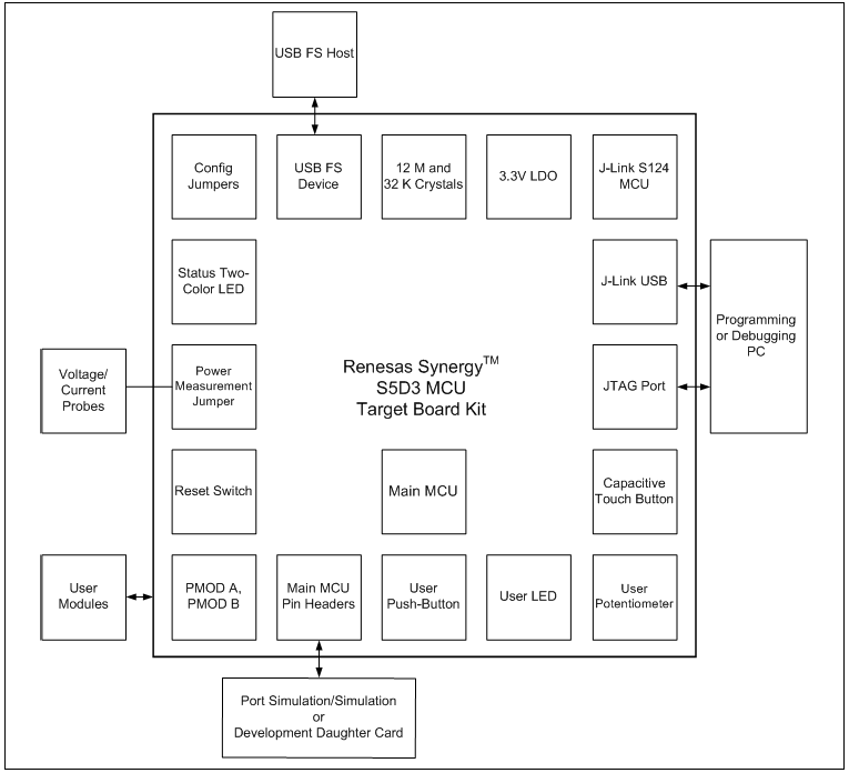
Block Diagram
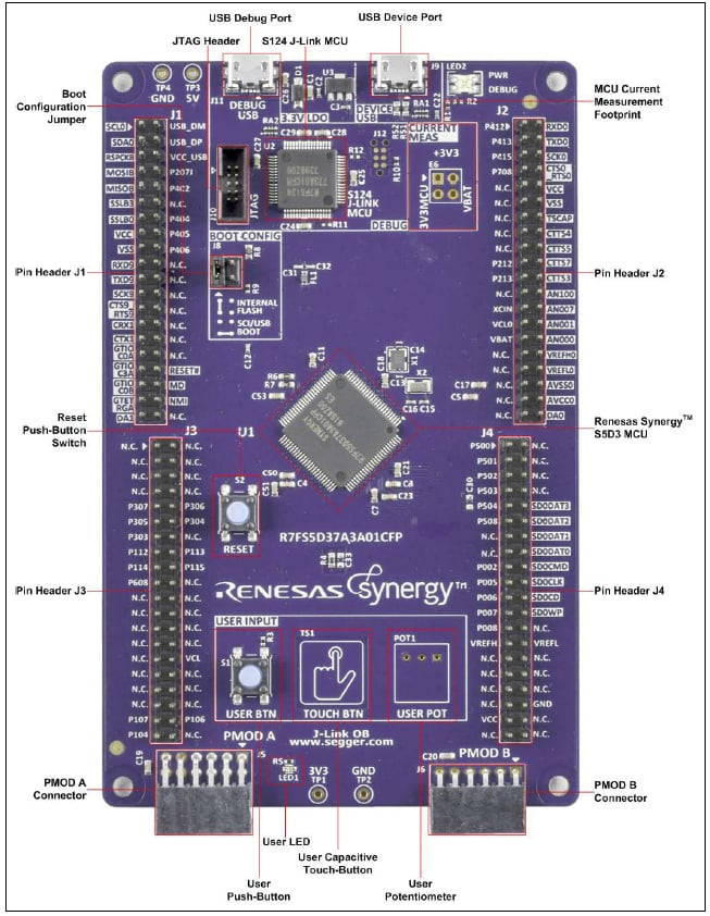
Front View
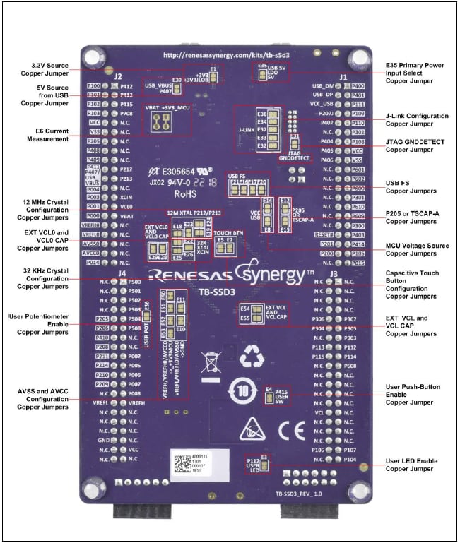
Back View
RELATED POSTS
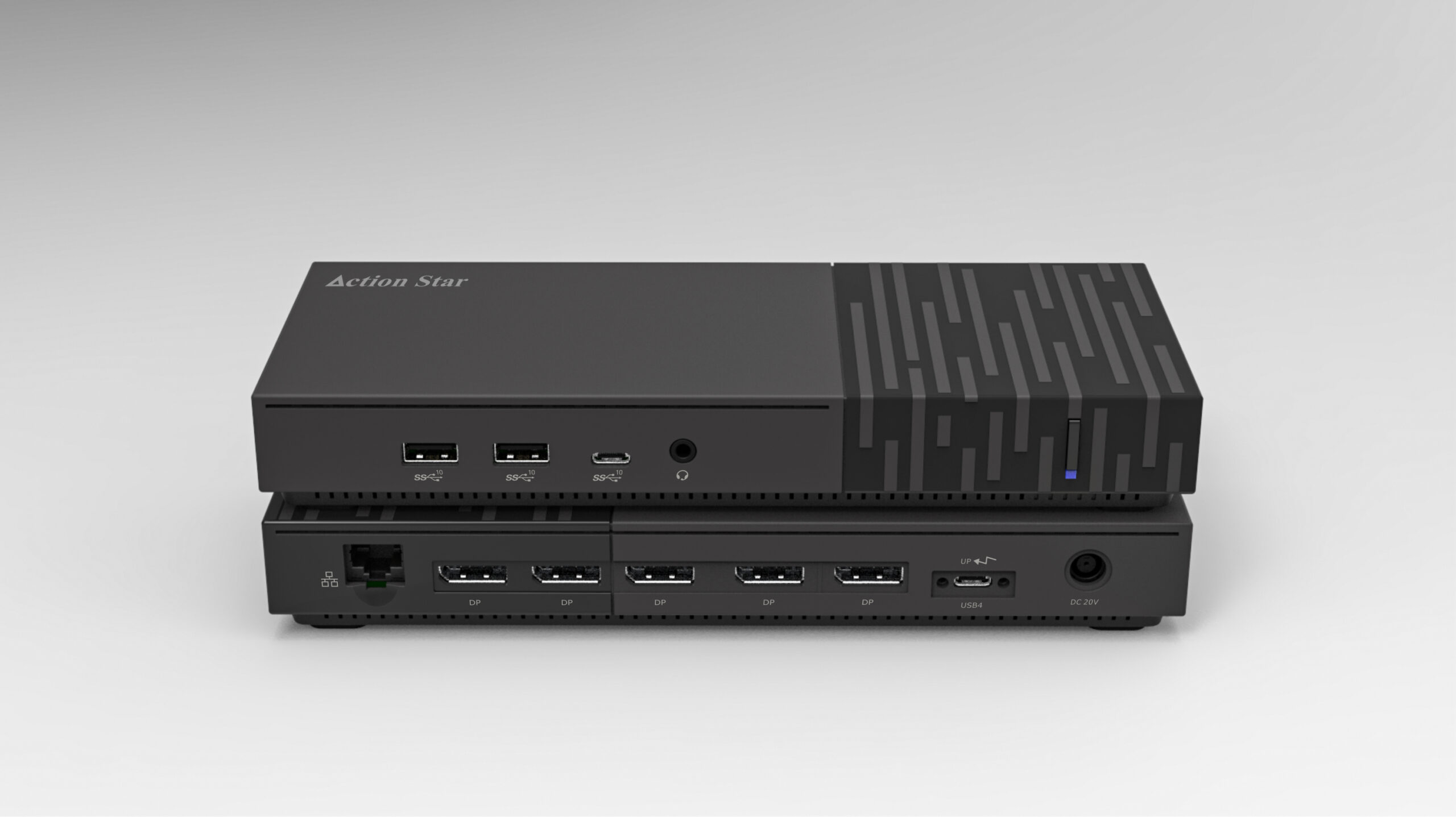 24 May, 2023 Action Star’s USB4 Penta-4K120 docking station at Computex 2023
 11 August, 2023 Nexperia unveils industry’s first coin cell battery life and power booster
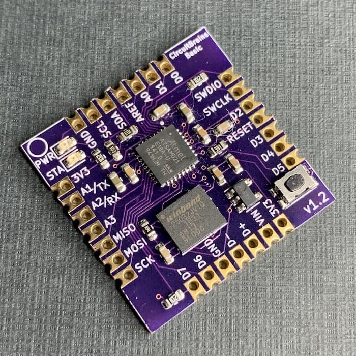 17 February, 2020 CircuitBrains boards, castellated modules coming soon …
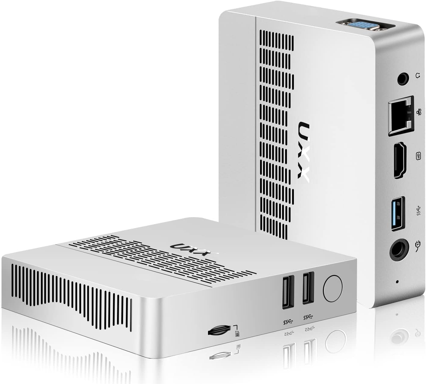 8 October, 2023 Apollo Lake Returns with a $89 Intel Celeron N3350 Mini PC featuring 6GB RAM and 64GB Storage
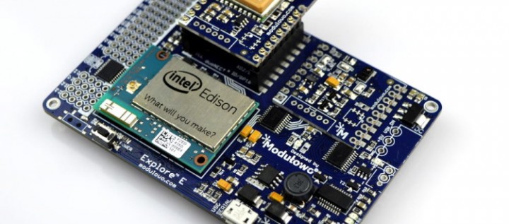 8 December, 2015 Universal shield for popular platforms Raspberry Pi, Arduino, Intel Edison
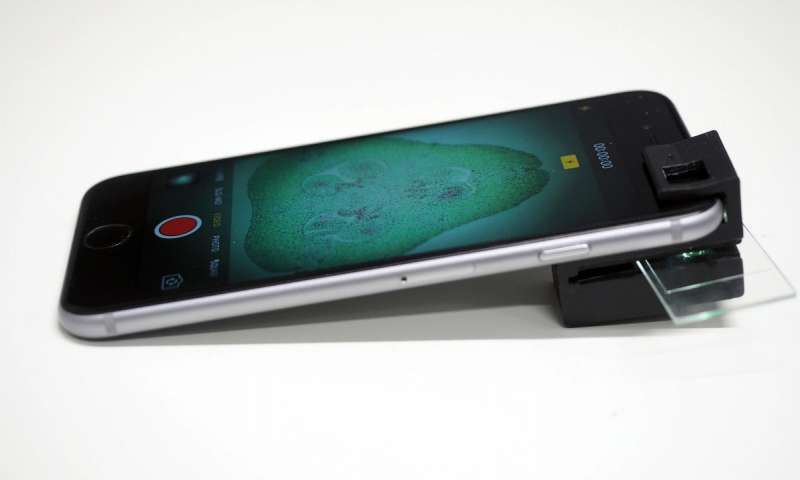 16 March, 2018 3D Printed Clip-On Turns Any Smartphone To A Household Microscope.


