Sensors and Transducers
Introduction Transducers are devices that change one kind of energy into another. They can be utilized as an output from an electrical circuit or as an input.
Introduction
Transducers are devices that change one kind of energy into another. They can be utilized as an output from an electrical circuit or as an input. A sensor is a device that detects and measures a physical quantity, such as temperature, pressure, or light, and converts it into an electrical signal.
In all electronic and control systems, sensors and transducers—input and output devices, respectively—are essential parts that enable the system to measure or alter its surroundings, depending on the device in use.
However, an electronic circuit or system must be able to connect with the “real world” to carry out any useful activity or function. Whether the task involves turning on an output device to switch on a single light or receiving an input signal from a switch (ON/OFF).
In other words, sensors and transducers are the essential parts of an electronic system or circuit, which must be able to perform any task.
In this context, both sensors and actuators are referred to as “transducers.” Sensors may detect a wide array of energy types, including thermal, magnetic, radiant, electrical, and movement energy. Actuators, however, can change output voltages, currents, or states.
Analog and digital sensors and transducers come in a wide variety, with both input and output variants to select from. The kind of signal or process being “Sensed” or “Controlled” truly determines the sort of input or output transducer being employed. Devices that can change one physical quantity into another are known as transducers.
Devices that carry out an “input” function are often referred to as sensors because they can “sense” a change in a physical property that alters how they react to external stimuli. Heat or a force, for instance, can be converted into an electrical signal. Actuators are typically defined as devices that carry out an “Output” function and can be utilized to regulate an external action. For instance, sound or motion.
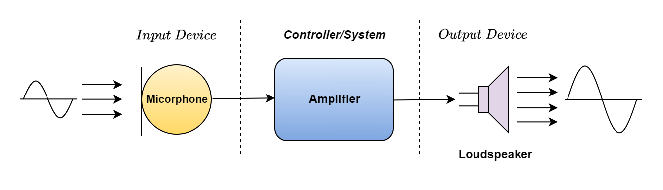
Therefore, electrical transducers are utilized to change one type of energy into another. A loudspeaker (an output device) transforms the electrical signals back into sound waves and a microphone (an input device) transforms the singer’s sound waves into electrical signals for the amplifier to amplify (a process).
An illustration of this kind of basic input/output (I/O) system is given below.
Simple Input/Output System
The electronics industry offers a wide variety of sensors and transducers, which are often categorized according to the measurement required, i.e. physical, chemical, or biological. Therefore, the quantity being measured or controlled truly determines the sensor to employ; the main popular varieties are shown in the table below:
Common Sensors and Transducers
The output response of input-type transducers or sensors is a voltage or signal that is proportionate to the change in the quantity being measured (the stimulus). The kind of sensor being utilized determines the kind or magnitude of the output signal. However, in general, sensors may be divided into two categories: passive sensors and active sensors.
Active sensors often need an external power source to function; this power source is known as an excitation signal, which the sensor uses to generate its output signal. When an external influence occurs, active sensors alter their characteristics to provide an output signal. For instance, an output current of 4 to 20 mA DC or an output voltage of 1 to 10 v DC. Additionally, active sensors can generate signal amplification due to their power supply needs.
An LVDT sensor or a strain gauge are excellent examples of active sensors. An externally biased (excitation signal) strain gauge is a pressure-sensitive resistive bridge network that generates an output voltage proportional to the mechanical force and/or strain applied to the sensor.
A passive sensor doesn’t require an extra power source or excitation voltage as an active sensor does. Rather, a passive sensor responds to an external stimulus by producing an output signal. For instance, a thermocouple, when heated, produces its voltage output. Passive sensors are direct sensors that alter physical characteristics like inductance, capacitance, or resistance, among others.
Digital sensors, in contrast to analog sensors, generate a discrete output that represents a binary number or digit, such as a logic level of “0” or “1.”
Analogue and Digital Sensors and Transducers
Analogue Sensors
A continuous output signal or voltage that is typically proportional to the quantity being measured is produced by analog sensors. Due to their tendency to be continuous, physical quantities like temperature, speed, pressure, displacement, strain, etc. are all analogous.
For instance, a thermometer or thermocouple, which continually reacts to temperature changes as the liquid heats or cools, may be used to measure the temperature of a liquid.
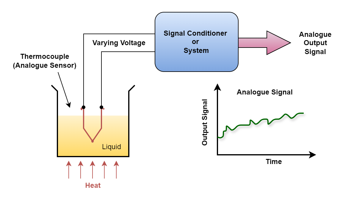
However, keep in mind that a mercury thermometer uses thermal expansion to modify the volume of mercury in response to a temperature change; this process results in a mechanical or visible displacement rather than an electrical signal.
The output signals from analog sensors typically change gradually and smoothly over time. Since these signals typically have values between a few microvolts (uV) and several millivolts (mV), some kind of amplification is necessary.
Analog signal measurement circuits are typically sluggish to respond and/or inaccurate. Additionally, analog-to-digital converters, or ADCs, make it simple to transform analog signals into digital signals for use in microcontroller systems.
Digital Sensors
Digital sensors, as its name suggests, generate discrete digital output signals or voltages that reflect the quantity being measured digitally. The binary output signal from digital sensors is either a logic “1” or a logic “0,” or “ON” or “OFF.” Accordingly, a digital signal only generates discrete (non-continuous) values, which can be produced as a single “bit” (serial transmission) or as a single “byte” (parallel transmission) by combining the bits.
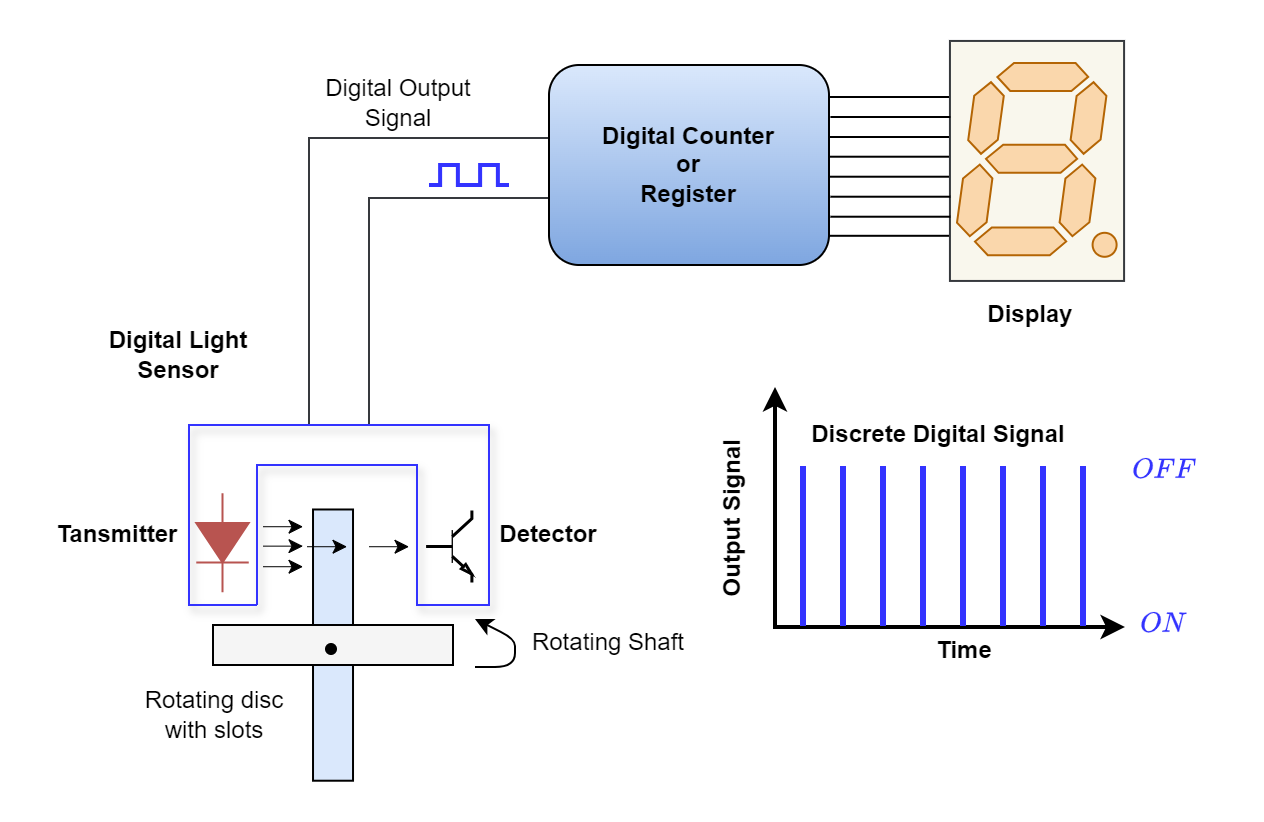
In our basic example above, a digital LED/Opto-detector sensor is used to measure the speed of the spinning shaft. There are several clear holes in the design of the disc, that is attached to a rotating shaft (such as from a motor or robot wheels). Each slot that the disc passes by the sensor in turn generates an output pulse that represents a logic “1” or logic “0” level as it spins in conjunction with the shaft’s speed.
To show the shaft’s speed or rotations, these pulses are first routed to a register of counters and then to an output display. More output pulses can be generated for every shaft revolution by expanding the disc’s slots, or “windows.” The benefit of this is that fractions of a revolution may be detected, leading to increased resolution and accuracy. With one of the disc holes serving as a reference location, this kind of sensor combination might potentially be utilized for positioning control.
Digital signals or quantities may be monitored and “sampled” at a very high clock speed and have extremely high accuracies when compared to analog signals. The amount of bits utilized to represent the measured quantity determines how accurate the digital signal is. An 8-bit processor, for instance, provides an accuracy of 0.390% (1 part in 256). A 16-bit processor, on the other hand, provides 0.0015% precision (1 part in 65,536), or 260 times higher accuracy. Because digital values can be processed and modified millions of times quicker than analog signals, this precision can be preserved.
To provide an electrical signal that is appropriate for measurement or use, sensors—more especially, analog sensors—usually need an external power source in addition to some kind of extra signal amplification or filtering. Operational amplifiers, as previously mentioned, are a very good approach to do both amplification and filtering in a single circuit.
Signal Conditioning of Sensors and Transducers
As demonstrated in the Operational Amplifier lesson, op-amps may be linked in either non-inverting or inverting arrangements to provide signal amplification.
A basic op-amp circuit can greatly increase the very small analog signal voltages generated by a sensor, such as a few millivolts or even picovolts, to create a much larger voltage signal, say 5v or 5mA, which can then be used as an input signal to a microprocessor or analog-to-digital system.
A sensor’s output signal must therefore be amplified using an amplifier with a voltage gain of up to 10,000 and a current gain of up to 1,000,000 to produce a useful signal. The amplification process must be linear, and the output signal must be an exact reproduction of the input, but with a change in amplitude.
Then, signal conditioning includes amplification. Therefore, before the signal can be utilized with analog sensors, it is usually necessary to do some sort of amplification (Gain), impedance matching, isolation between the input and output, or maybe filtering (frequency selection). Operational amplifiers are a practical way to accomplish this.
Additionally, a sensor’s output signal may get “contaminated” with undesired signals or voltages when sensing extremely little physical changes, making it impossible to accurately measure the needed signal. “Noise” is the term for these undesired impulses. As we covered in the Active Filter course, signal conditioning or filtering techniques may either significantly reduce or even eliminate this noise or interference.
The “bandwidth” of the noise can be decreased to leave only the output signal needed by employing a Low Pass, High Pass, or even Band Pass filter. For instance, a low-pass filter can be utilized since numerous input types like switches, keyboards, or manual controllers are not able to change states quickly. Narrowband reject or notch filters can be used to create frequency-selective filters when the interference occurs at a certain frequency, such as the mains frequency.
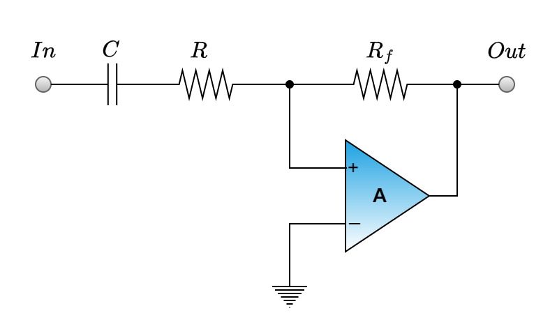
Typical Op-amp Filters
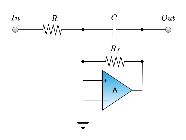
Taking many samples and averaging them to provide the final result may be required if some random noise persists after filtering, hence raising the signal-to-noise ratio. In any case, amplification and filtering are crucial for connecting sensors and transducers to electronics and microprocessor-based systems in “real world” settings.
Positional sensors, which monitor the position and/or displacement of physical objects—that is, the movement from one location to another for a certain distance or angle—will be covered in the next sensor lesson.
Conclusion
- Transducers convert one type of energy into another and are categorized as input (sensors) or output (actuators) devices. Sensors detect and measure physical properties like temperature or pressure, converting them into electrical signals, while actuators regulate external actions.
- Sensors and transducers are classified as analog or digital and active or passive. Analog devices produce continuous signals, while digital ones generate discrete signals. Active sensors require an external power source, whereas passive sensors generate signals from external stimuli.
- Amplification and filtering are essential for processing sensor outputs. Operational amplifiers are commonly used to enhance small analog signals and filter out noise, ensuring precise measurement and compatibility with digital systems.
- Applications include microphones converting sound waves into electrical signals and loudspeakers performing the reverse process. Sensors like thermocouples and strain gauges demonstrate practical uses in measuring physical properties and enabling system control.
- Digital sensors provide higher accuracy and resolution, with discrete binary outputs suitable for microprocessors. Analog sensors, though continuous, require conversion to digital signals for precise processing. Both types play critical roles in electronic and control systems.


