Leaderboard

Popular Content
Showing content with the highest reputation since 07/27/2015 in Posts
-

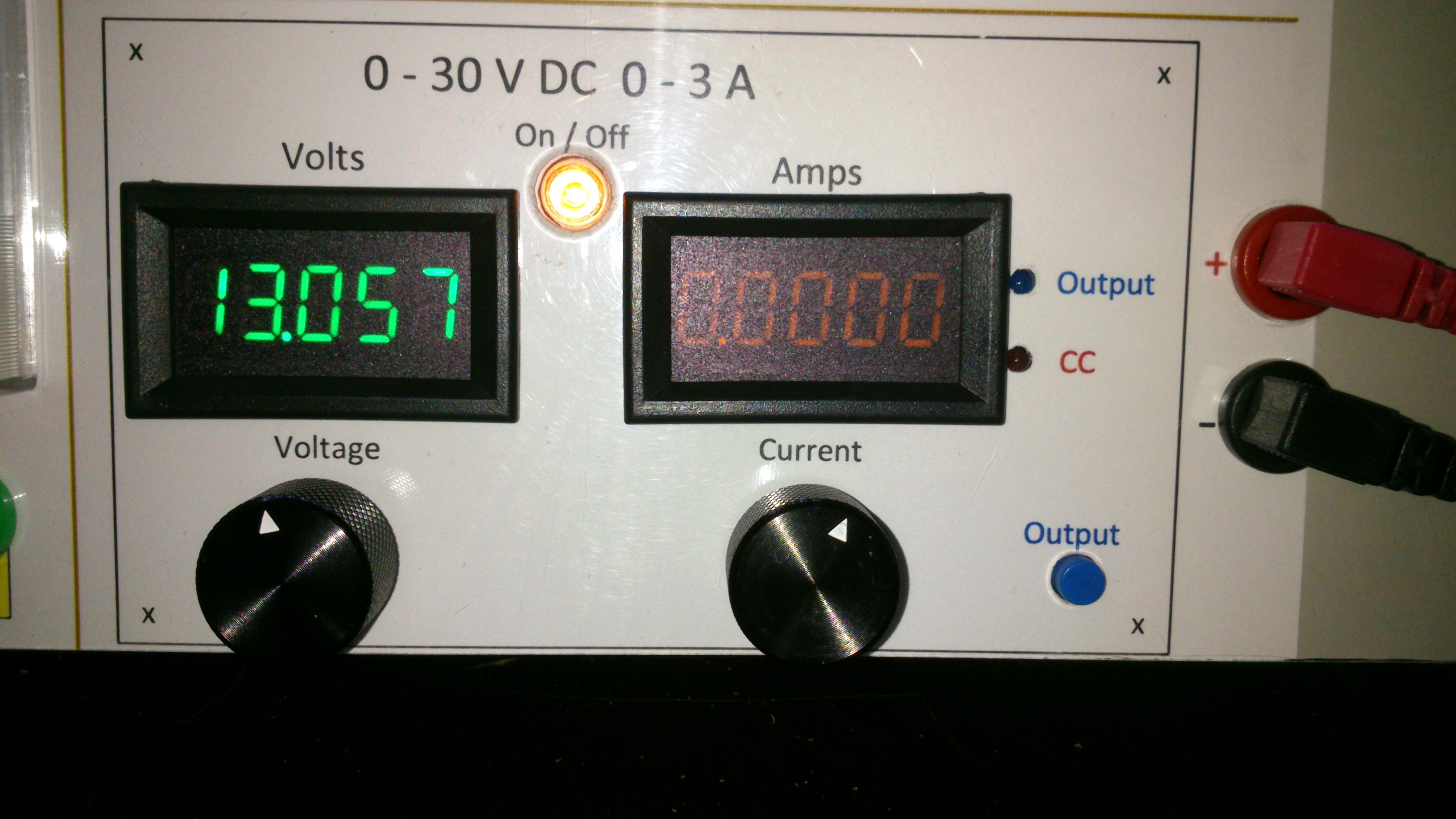
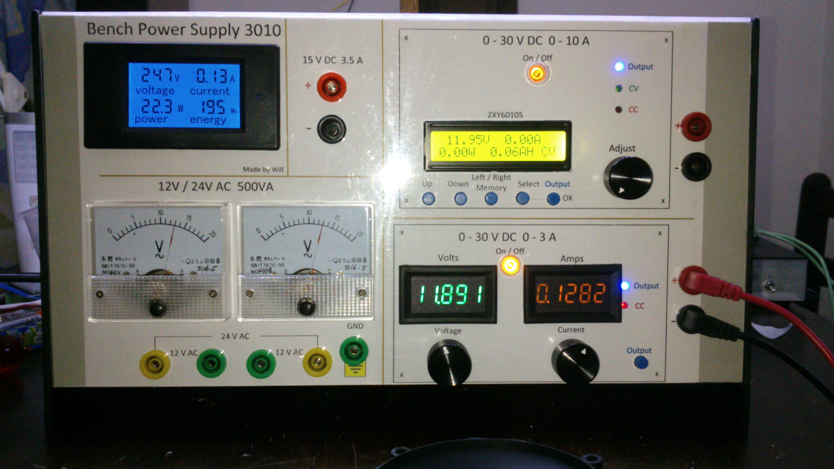
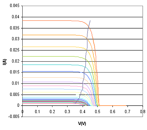
0-30V 0-3A Latest Data
AsSa and 3 others reacted to repairman2be for a topic
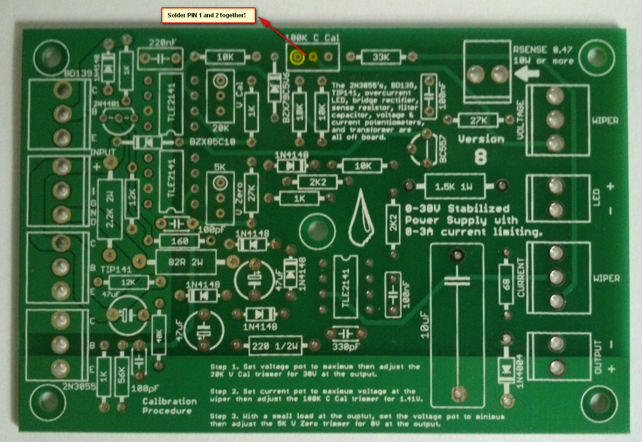
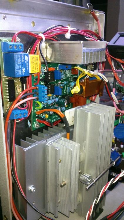
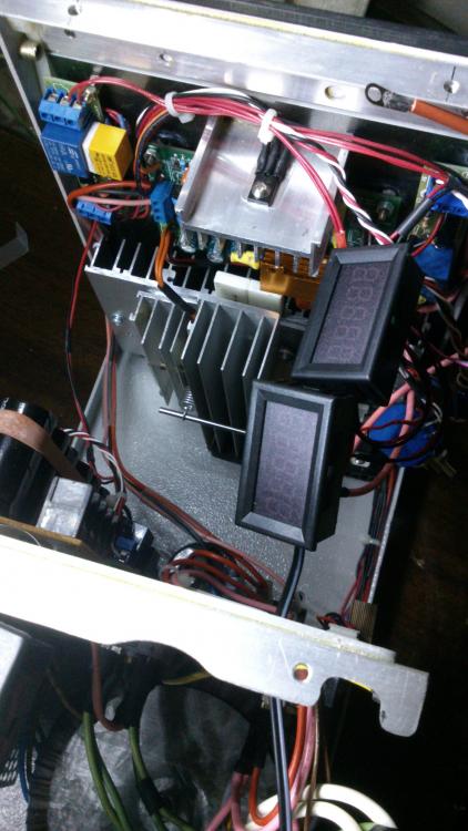
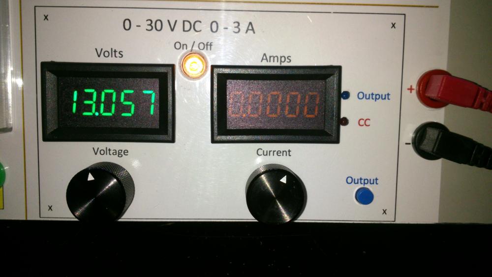
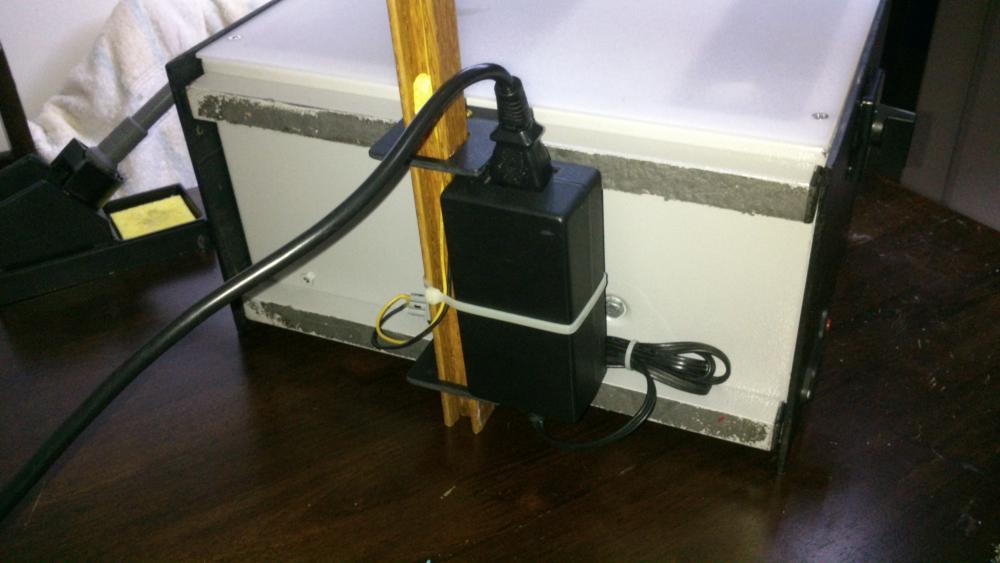
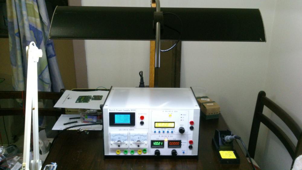
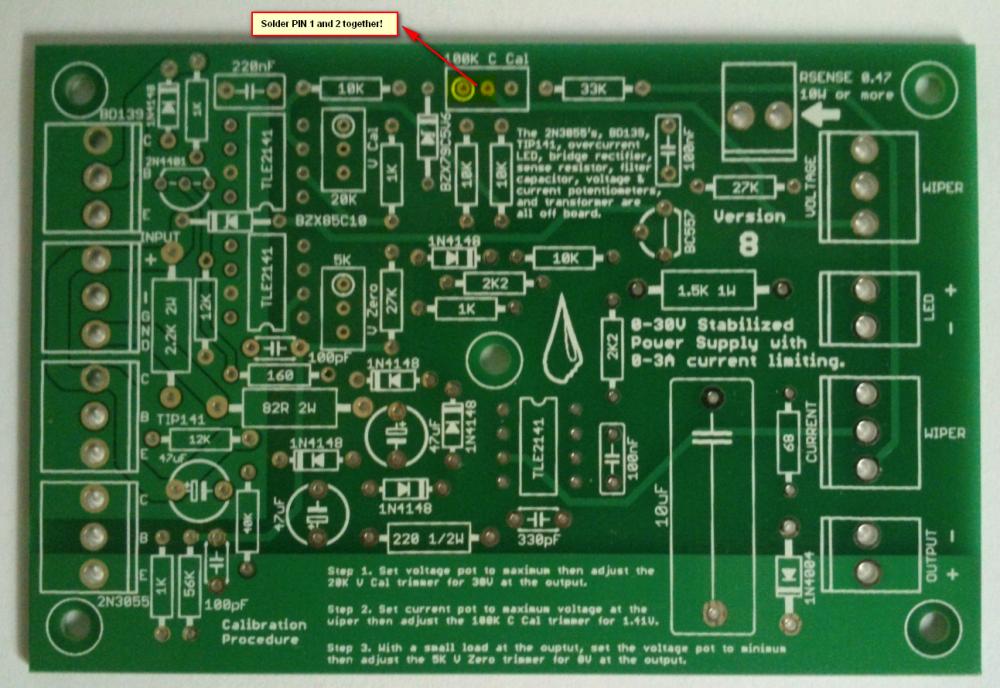
Hi all, Finally after some months have gone by, my build of the Power Supply is done. I have used liquibyte schematic Rev. 8 and had made the cirquit board according to the Gerber.zip file he posted here: 0-30V Stabilized Power Supply Page 88 posted October 6, 2014 "http://electronics-lab.com/community/index.php?/topic/29563-0-30v-stabilized-power-supply/&page=88" I left out D10 and R15 as per his description. I have plenty of boards leftover if someone has a need for it. There was only one mistake liquibyte made which have outlined in one of the pictures uploaded here. I was fortunate enough to get a big case with a Toroidal transformer from the scrapyard. Also many parts are recycled from various sources. Regards, William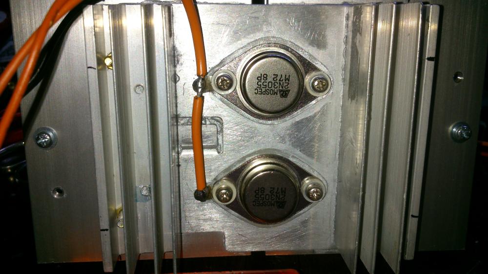

 4 points
 -
Finally, my post with the Eagle .sch and .brd, full gerbers, and parts list for Digikey in a zip file. I'm also including many of the pics I took as I was building that were posted both before and after this post. I'm still not completely done and may add more pics later. One thing I have changed is the third transformer for the auxiliary circuitry for the temperature sensor and fans and the displays (I wanted a better transformer than the Radio Shack special I had on hand). Archive attached. 30V.zip
 3 points
 -

Solar-powered Bee Hotel w/ Particle Argon (ongoing project)
Jolin He and one other reacted to JamesMVictoria for a topic
Nice one, I like it.2 points -

How to easily turn on/off all debug message on Arduino IDE
SharonWatkins and one other reacted to MrNams for a topic
But even if we disable debug, it will call print method and do not print anything. I mean we should make it something like #ifdef DEBUG Serial.print("\n debug controlled print"); #endif Here when we disable macro, its like code is not written for compiler, code will be removed in macro processing itself.2 points -

H Bridge PWM DC Motor Driver + PCB
senaka ranathunga and one other reacted to sam.moshiri for a topic
An H-Bridge (Full-Bridge) driver is quite popular in driving loads such as brushed DC motors and it is widely used in robotics and industry. The main advantages of using an H-Bridge driver are: high efficiency, rotation direction change, and braking the motor. In this article/video, I have introduced a complete H-Bridge DC motor driver using four IR3205 power MOSFETs and two IR2104 MOSFET drivers. Theoretically, the above-mentioned MOSFET can handle currents up to 80A, however, in practice we can expect to get currents up to 40A if the MOSFET temperature is kept as low as possible, using a big heatsink or even a fan. References Article: https://www.pcbway.com/blog/technology/Powerful_H_Bridge_DC_Motor_Driver.html [1]: IRF3205 Datasheet: http://www.irf.com/product-info/datasheets/data/irf3205.pdf [2]: IR2104 Datasheet: https://www.infineon.com/dgdl/Infineon-IR2104-DS-v01_00-EN.pdf?fileId=5546d462533600a4015355c7c1c31671 [3]: 1N5819 Datasheet: https://www.diodes.com/assets/Datasheets/ds23001.pdf [4]: IR2104 Schematic Symbol, PCB Footprint, 3D Model: https://componentsearchengine.com/part-view/IR2104PBF/Infineon [5]: IRF3205 Schematic Symbol, PCB Footprint, 3D Model: https://componentsearchengine.com/part-view/IRF3205ZPBF/Infineon [6]: CAD Plugins: https://www.samacsys.com/library-loader-help2 points -

Non Contact Hand Sanitizer Dispenser, Easy, Cheap, No Arduino!
sam.moshiri and one other reacted to admin for a topic
Thanks for sharing your project with us. Could you give more details on the control board?2 points -
The original circuit should work fine up to 15V at 1A if you replace the old opamps with the newer higher voltage ones. You probably should recalculate the resistors that set the maximum voltage and current outputs. If the Chinese kit uses the transistor that shorts the opamp output when the power is turned off then the resistors that feed the transistor need to be recalculated for the reduced voltage. I have used perforated stripboard for many projects including very complicated ones. The copper strips are cut to length with a drill-bit and become almost half the wiring of a pcb. The parts and a few short jumper wires become the remainder of the wiring. Only one wire is in each hole so changing a part is easy like on a pcb.2 points
-
Hi, as promised I made an English translation of my working. Maybe there is few mistakes and I am sorry for that ! Good reading. ExplicationEN.pdf2 points
-
I use copper wire, not rice wire. They put rice in everything they make, especially batteries.2 points
-

0-30 Vdc Stabilized Power Supply
electron234 and one other reacted to elctro123 for a topic
So Finally which version of schematic is correct / flawless to build the PSU ?2 points -
February 23 above on this page has the latest schematic of the revised 3A lab power supply.2 points
-
Does anyone has LM3914 pspice library? i desperately need it..pleeeeease!2 points
-

Low power solenoid?
AmelieScott and one other gave a reaction for a topic
I want to apply force for an extended amount of time (10 secs to a couple minutes) using a solenoid actuator. Unfortunately, it seems that solenoids use a lot of power when they are active. Is there a solenoid type that will only use power when switching between active and not active? There's probably a way I can do this with an external mechanism, but I was wondering if there may be commercial solenoids that have this built-in. Thanks, Jessica2 points -
Illegal content (ebook/magazines/software) will be deleted without any notice. Thanks2 points
-

Overload Protector A16 ???
joeydennis11 and one other reacted to tjolle62 for a topic
In a few circuit diagrams i have they refer to a what seems to me is a transistor with B C E as a overload protector and with number A16 and i have looked for a few hours on the net and i can't find anything on this little fellow, Anyone knows what I'm looking for and wanna share that info Please .... Come on !! 48 visits !! some one must know what it is !!! PNP is it also...........2 points -
Overload Protector A16 ???
joeydennis11 and one other reacted to tjolle62 for a topic
At last i got a theori from a totally different place and he wasn't shure either but he had a weak memory that it could be 1A16 and a PNP transistor but after several deep searches on the I-net it didn't make any kind of senses whatsoever ???2 points -

Car battery to parallel port
tracythomas50 and one other reacted to MP for a topic
When you use your resistive divider to drop the voltage down to 5 volts, you just need to select values of resistors to limit the current. This is basic ohm's law. V/R. Was this your question or did I misunderstand? I am not sure how you intend to monitor status by using one 5 volt pin. As an interface to the parallel port, you could use an LM3914. This would give you the resolution you need. There are also many other ways to proceed. You need to convert from analog to digital to read anything useful from the parallel port. MP2 points -

Car battery to parallel port
tracythomas50 and one other reacted to Omni for a topic
Hi TJBraza, http://www.analog.com/UploadedFiles/Data_Sheets/ADT7485A.pdf Although, it will probably require a small program written in C or Visual basic to convert the string MSB & LSB into a more easier read etc... Take a moment and review the data sheet, the IC has a lot of potential.2 points -

SL100 & SK100 transistor
AmelieScott and one other reacted to alanng96 for a topic
I can't find SL100 & SK100 transistor :'( Which transistors can replace these? Thank you for your help~ ;)2 points -
Calm down people. It is not Mixos's fault, if it is against the law he has to remove the content. This site is very good for asking electronic related questions, I have yet to find a better one.2 points
-

How to Support Virtual Network on Linux 4.1.15?
BreanneJJustice reacted to Forlinx for a topic
Taking the FETMX6ULL-C platform as an example, if you want to use VPN, you need to open the tun configuration in the kernel in the following way: Kernel Compilation Choose either of the two methods below: 1. Modify the.config file directly Locate the.config file in the kernel source path. Find the CONFIG _ TUN in the file and modify it as follows: Replace the kernel's config file with .config. * Subject to actual use. Recompile the kernel. 2. Configure the TUN using the graphical configuration interface Make menuconfig. Locate the following locations: Save and exit after modification, which can be seen in.config Replace the kernel's config file with .config. * Subject to actual use. Recompile the kernel. Update kernel: The arch/arm/boot/zImage file is generated after compilation, and the kernel can be replaced either by updating the kernel separately or by re-burning it. Use this file to replace the file with the same name in the target path of the flashing tool. Refer to the single-step kernel update chapter of the FETmx6ull-c User's Manual to replace the zImage file separately. Compilation module: In the kernel source code, some of the drivers are compiled in the form of modules, which are loaded from the specified path by the kernel version number when the system boots. When we recompile the kernel and update the kernel, the kernel version number in the system will be changed, the kernel version number can be viewed through the uname -r command. When you update the kernel, the uname -r version number changes, but the version number in the path where the module is stored (/lib/modules/) does not change. It may cause the module to fail to load, typically after updating the kernel, WiFi cannot be used. As seen below, the name under uanme -r and the name under /lib/modules/ are not the same, so you can't load the module when you go to the/lib/modules/$(uname -r) directory when booting up, and you need to change both names to be the same. You can solve this problem in two ways: 1. Modify the module load path and change to the version number of the kernel; 2. Repackage modules; The first method has two disadvantages: a. Not suitable for batch modification; b. Not suitable for changing the module driver; So it is possible to repackage the module when compiling the kernel: After executing the above operation, .tmp/root/modules.tar.bz2 will be generated, which can replace the file with the same name under the target path in the flashing tool. It is also extracted directly in the file system:1 point -

Please help to determine which silk screen is genuine
Marie P Cox reacted to HarryA for a topic
First off one can not read the text on the second IC. They claim fake ICs come in two types; those that are commercial grade and sold as military grade. And those that are used from discarded equipment. The latter type may well have the correct text on them. I gather they do not manufacture fake ICs as they are too inexpensive to be bothered with.1 point -

Good book for beginners?
tommyhanks2 reacted to ernander123 for a topic
what else is there?1 point -

TensorFlow Lite - Magic Wand on RTL8722DM
Fahad Ibrahim reacted to Yahui Ji for a topic
Materials • Ameba D [RTL8722 CSM/DM] x 1 • Adafruit LSM9DS1 accelerometer • LED x 2 Example Procedure Connect the accelerometer and LEDs to the RTL8722 board following the diagram. Download the Ameba customized version of TensorFlow Lite for Microcontrollers library at ambiot/ambd_arduino. Follow the instructions at Arduino - Libraries to install it. Ensure that the patch files found at ambiot/ambd_arduino are also installed. In the Arduino IDE library manager, install the Arduino_LSM9DS1 library. This example has been tested with version 1.1.0 of the LSM9DS1 library. Open the example, “Files” -> “Examples” -> “TensorFlowLite_Ameba” -> “magic_wand”. Upload the code and press the reset button on Ameba once the upload is finished. Holding the accelerometer steady, with the positive x-axis pointing to the right and the positive z-axis pointing upwards, move it following the shapes as shown, moving it in a smooth motion over 1 to 2 seconds, avoiding any sharp movements. If the movement is recognised by the Tensorflow Lite model, you should see the same shape output to the Arduino serial monitor. Different LEDs will light up corresponding to different recognized gestures. Note that the wing shape is easy to achieve, while the slope and ring shapes tend to be harder to get right. Find out more at: https://www.amebaiot.com/en/amebad-micropython-periodical-timer/ Join in the community discussions at: https://www.facebook.com/groups/amebaioten https://forum.amebaiot.com/ Purchase links for the various Realtek development boards can be found at: https://www.amebaiot.com/en/where-to-buy-link/1 point -
I am working with CS5484 for a project and I am unable to configure the IC
Conor Torres reacted to HarryA for a topic
There is a library file ( GOLANG library for SPI ) here that maybe helpful? https://github.com/stamp/CS5484 I have problems finding the page that has the {code} button to download the file; you may have to dork around with the URL a bit.1 point -

Rheostat power rating
JamieOkeefe reacted to uziao for a topic
Hello friends. Very interesting topic you have here. You can model the electrodes underwater as an capacitor in parallel with a resistor (a leaky capacitor). Maybe this is why he used a bifilar coil... Bifilar coils are self resonant coils because of their capacitance. You can see this article here: https://sci-hub.st/https://doi.org/10.1002/cta.2830 The autor proposed a resonant tank circuit without the capacitor, using only the capacitance of the bifilar coil. If the electrodes underwater behave like a true capacitor, he wouldnt need 2 coils... Only one coil would do the job... Maybe the trick lies in the coils only...1 point -
Help identifying electronic components
Guy Shemesh reacted to HarryA for a topic
If you compare your board with the one on Ebay that one looks like the better board. You may gain some insight by comparing the P6? on your board with the three in the schematic and see if it connects the same as one of them. This is the schematic of the Viber12a in a battery charger.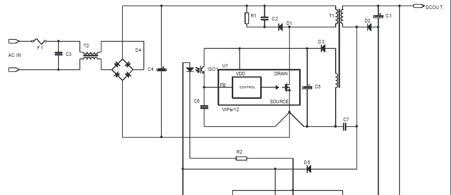
 1 point
 -
There is an article "Design Project2 - BCD Calculator" that maybe helpful. http://homepages.cae.wisc.edu/~ece352/fall02/old_project/p2.pdf1 point
-

Non Contact Hand Sanitizer Dispenser, Easy, Cheap, No Arduino!
sam.moshiri reacted to Sugandhan Vazhumuni for a topic
Thanks for Sharing1 point -
BMS Charger for 18650
gztoppower reacted to admin for a topic
This is the basic connection of BMS charger circuit. Do you need the scheme for the charger it self maybe?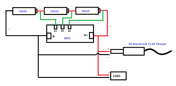 1 point
 -

PCBGOGO after-sale service review
dorrismillerrr123 reacted to KrisDong for a topic
The board is made very precisely, it's clean and very pleasant to touch. Markings on the silkscreen layer are very good readable. Soldering does not cause trouble, tin adheres very well to soldering points with a small amount of flux. It is also worth mentioning that the PCB is very robust to desoldering. The company is very solid, although you order 10 pieces, you get at least 1 PCB more for test, prototype, present, etc. When I signed up for an account, I also got a $20 coupon for free. Excellent construction and assembly work done by PCBgogo.No problems encountered, highly recommended.1 point -
Need Help: Bluetooth External Camera controlled by iPhone app
aleksczajka reacted to HarryA for a topic
Perhaps? To big? " This Fujifilm FinePix digital camera has Bluetooth connectivity for wireless media transfer. " https://www.bestbuy.com/site/fujifilm-finepix-xp130-16-4-megapixel-digital-camera-sky-blue/6204739.p?skuId=62047391 point -
One 2N3055 transistor overheats in the original circuit that used a 24VAC transformer and produces 25VDC at 3A. Therefore I used higher voltage opamps, a 28V 4.2A transformer, a more modern driver transistor Q2 that can be cooled well and two 2N3055 transistors to share the heat on a very large heatsink. Some people added a fan and a smaller heatsink instead of a huge heatsink. If you connect the two 24V windings of your transformer in series and use the centertap as 0V then its output voltage will be 24VAC x 1.414= 34V minus the 1V for the two rectifiers then the supply voltage will be too low because the circuit needs a 28VAC transformer. Your transformer voltage is too high so it cannot be used for this project. Or you could parallel the two 24VAC windings or with the centertap as above then the maximum regulated output voltage will be 25VDC at 3A.1 point
-

BGA rework Process?
hunghoang reacted to soldertools1 for a topic
Hey, I also found a training institute and an article about BGA Rework Process. Follow the given link below to get a clear understanding of reworking BGA process: http://www.solder.net/services/bga-rework-services/1 point -

DIY - ARDUINO BASED CAR PARKING ASSISTANT
davidjackson reacted to Ashish Adhikari for a topic
1 point -
Since it was years ago I do not remember which page of which thread has version 6 or 7. I have the schematic and parts list of version 6 here:
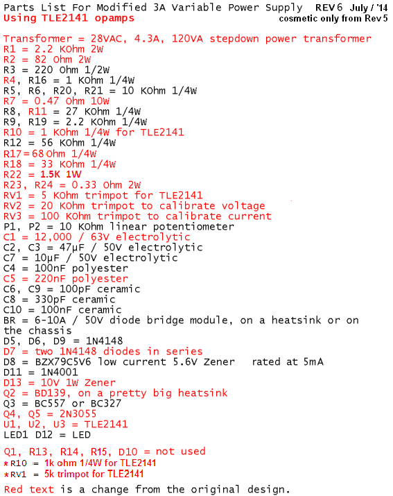
 1 point
 -

clipping circuit
soldertools1 reacted to Soldertraining for a topic
The clipping circuit does not have energy storage elements like capacitors but it includes both resistors and transistors. This circuit is normally used for the selection in the transmission purpose. The ability of diodes to allow the flow of current in only one direction. A diode is best tested by measuring the voltage drop across the diode when it is forward-biased. A forward-biased diode acts as a closed switch, permitting current to flow. No voltage exists at the diode but voltage may be present in the circuit due to charged capacitors.1 point -
high value blue color capacitor
hugomulls reacted to Soldertraining for a topic
The colors of capacitors describe the types of capacitors. The color used to identify the components or parts on the circuit board. The round blue colored balls with dots indicate that its a capacitor. Same as other colors are used for other components.1 point -
0-30 Vdc Stabilized Power Supply
HaddyS reacted to repairman2be for a topic
@Jeremy You may have 2 PCB's for AU$5 plus shipping in an envelope. Two boards weigh about 44grams. Email me if you would like some to: [email protected] Cheere, William PS. Seems your Kit has a problem to start with. Before I found this Forum I ordered two Banggood Kits. It is still not assembled and probably never will be. Anyway, over at this page there is a lengthy description on how to improve the Banggood kit. "www.paulvdiyblogs.net/2015/05/tuning-030v-dc-with-03a-psu-diy-kit.html"1 point -

ARMA IoT-wifi shield for Arduino
JolynObjecy reacted to vishwas95 for a topic
Are u looking for a way to connect the Arduino to the internet easily? Do you want to develop your IoT project quickly without much hassle? ARMA IoT might just be the thing for you! The simple and efficient Arduino shield is powered through a esp12f wifi module, which enables it to be connected to the wifi network. it also has an SD card slot for for extra data storage like its wired brethren the Ethernet Shield. The ARMA IoT goes a step further and provides an easy plug and play feature for most of the common devices such as sensors, motors, LCDs and relays. The ARMA IoT is a great place for beginners to start their IoT project, as it requires minimum time to setup the hardware all thanks to the plug and play feature. Even the programming is simplified through the help of apps such as Blynk, which provides easy feature of controlling the Arduino through your Android or iOS phone. Thingspeak an upcoming IoT platform is also supported by the shield. The ARMA IoT platform proves as a tool for aspiring beginners and also a prototyping tool for advanced users. IoT products can be developed much faster with the help of this board. Weather it is creating a simple IoT project such as blinking LEDs or controlling relays, or developing your own Home automation system, the ARMA IoT facilitates it all and things seem to happen rather quickly with all the features provided on the board. The wifi connection feature can provide fast communication between devices or two instances of ARMA itself, making it applicable for simple swarm robotics, wireless controllers etc. The applications can also be extended to simple robotics, Energy management systems and it does not stop there as it all depends upon the users creativity. To get started simple tutorials are provided on the YouTube page of ARMA IoT, the link below guides on the setup of Arduino and ARMA IoT with the help of Blynk app More tutorials and projects will be posted to help you make the most of the shield. Of Course there are also various DIY communities that can provide you with both support and inspiration for your upcoming IoT projects. thus ARMA is another simple board that has the ability to bind many devices together. The ARMA IoT is still undergoing a crowdfunding campaign in Indiegogo and is available for pre-order. https://www.indiegogo.com/projects/arma-iot-breakout-board-for-arduino#/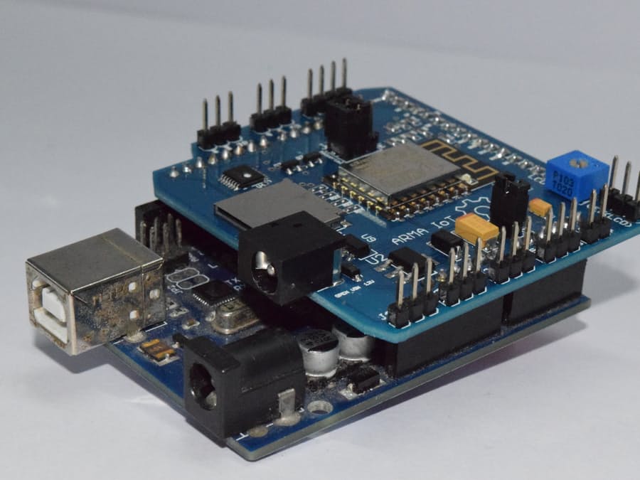
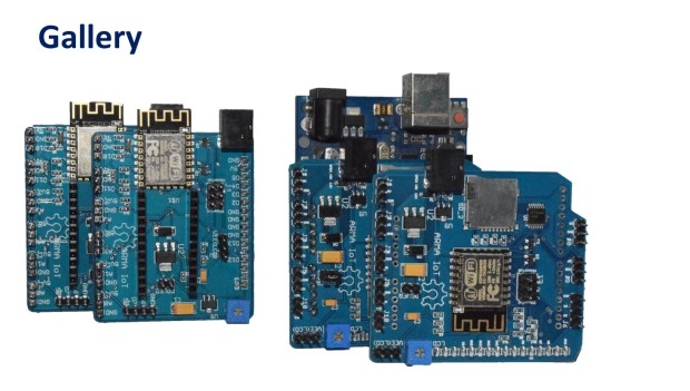
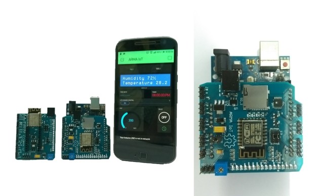 1 point
 -

Sensor alarm and transmitter
Jacquelyn Norris reacted to steve10101 for a topic
Hiya, I now cant find the projects I found yesterday sorry... but the below link is a device similar to what I'm looking for, but I'm looking to make this work in reverse (hoping this may help). The distance I'm trying to achieve would be for the alarm to activate if transmitter was anything from 0-10 feet away. http://www.pimall.com/nais/rdiftagalert.html1 point -

Power conversion
Cory D reacted to Bob Wettermann for a topic
"A solar charging system is not complete without an appropriate charge controller. Most units include a charge controller to charge 12-volt lead acid batteries and inverter for drawing power. Charge controllers are also available for lithium-ion to charge 10.8V packs (3 sells in series)." 1 point
 -
The output of a preamp will produce clipping distortion if the input level is too high. The pickup from an electric guitar produces a level much higher than an FM tuner, a CD player or an MP3 player. Most preamps for a guitar pickup use a Jfet because of its very high input impedance with a gain of only about 1.4 times.1 point
-
I don't know about function but it certainly seems like it's trying to look like it. I get why he wants everything integrated and looking the same but I despise the web 2.0 look. The first person to do this was doing something unique, everyone else, not so much.1 point
-

What's happened to all the posts since 24 February?
admin reacted to bilalmalikuet for a topic
yes its looks more better1 point -
The current rating is not a problem. It's better to go higher than lower. Using a power relay to switch low current signals is only a problem at very low voltages. The problem with using a lower voltage relay is the contacts can arc over and what's worse it it could be unpredictable.The relay may seem fine most of the time but it could suddenly arc over due to ambient ionising radiation.1 point
-

High Voltage low amperage
HaddyS reacted to Kevin Weddle for a topic
Generating a very high voltage with a small battery is an interesting idea. In theory, a transformer can produce any voltage, depending on it's turn ratio. They can also be cascaded. Are there any designs that utilize cascaded transformers, and if so, why isn't one transformer used?1 point -
All that means is that if the capacitor is too small, it won't be large enough to damp the oscillations but if it's a single, large value capacitor it won't be good either. Higher value capacitors tend to have poor high frequency characteristics and become inductive past the resonant frequency, the higher the value, the lower the resonant frequency. Rather than using a single, high value capacitor, it's better to use a large capacitor and lower value capacitor in parallel with one another. The type of capacitor is also important; for example tantalum is better than electrolytic. I'd recommend a 1uF tantalum in parallel with a 100nF and 10nF ceramic capacitor on both the input and output. If you don't have a 1uf tantalum, go with 22uF electrolytic.1 point
-

Tesla with A811 tube
JerryAcert reacted to ptkindt for a topic
I made a Tesla transformer with a A811 tube. I did not force anything, it can run for hours. The making of: http://www.youtube.com/watch?v=H7nivw7zxNM The result: http://www.youtube.com/watch?v=Mp721VgxWQI1 point -
after removing of ebook files, the page is not visited so much and not updated messages as before...1 point