Programming ESP8266 With Arduino IDE : The Easy Way
The ESP8266 WiFi Module is a self-contained SOC that can give any microcontroller access to your WiFi network. It's an extremely cost-effective board with a huge and ever-growing community.
The ESP8266 WiFi Module is a self-contained SOC that can give any microcontroller access to your WiFi network. It’s an extremely cost-effective board with a huge and ever-growing community. Each ESP8266 module comes pre-programmed with an AT command set firmware. This module has a powerful on-board processing and storage capability that allows it to act as a standalone microcontroller.
Following 2 easy steps, you can upload Arduino sketches on your ESP8266 using Arduino IDE.
- Configuring the IDE
- Making the circuit
Parts List
- ESP 8266 Module.
- Jumper wires.
- A breadboard.
- One USB to TTL converter, a.k.a UART converter.
Configuring The IDE
In order to bring support for ESP8266 chips to the Arduino environment, you need to add ESP8266 Arduino Core in the IDE.
- Install Arduino 1.6.8.
- Start Arduino and open Preferences window.
- Enter
http://arduino.esp8266.com/stable/package_esp8266com_index.jsoninto Additional Board Manager URLs field. (See the first image) - Open Boards Manager from Tools > Board menu and install ESP8266 platform. (See the second image)
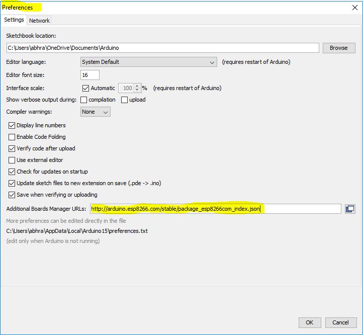
Add URL to “Preferences” in Arduino IDE (as shown in cover screenshoot)
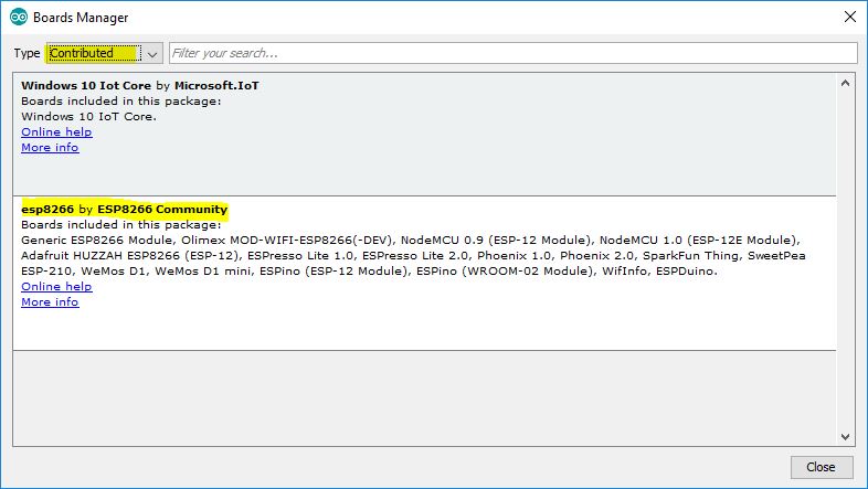
Select ESP8266 board from Board Manager (as shown above)
Making The Circuit
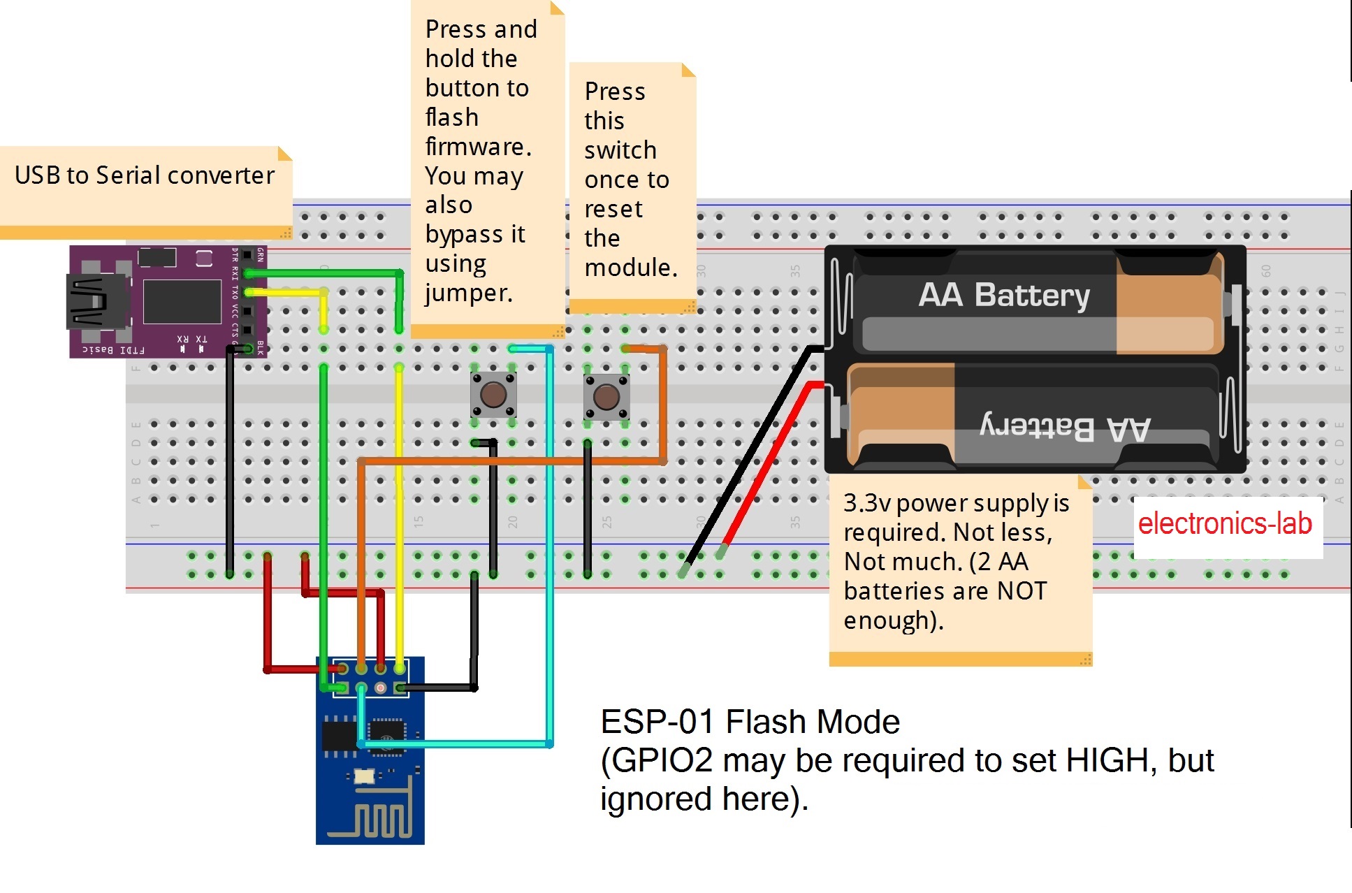
ESP-01:
- Connect GPIO0 to Ground (set it LOW or 0)
- Connect CH_PD toVcc (set it HIGH or 1)
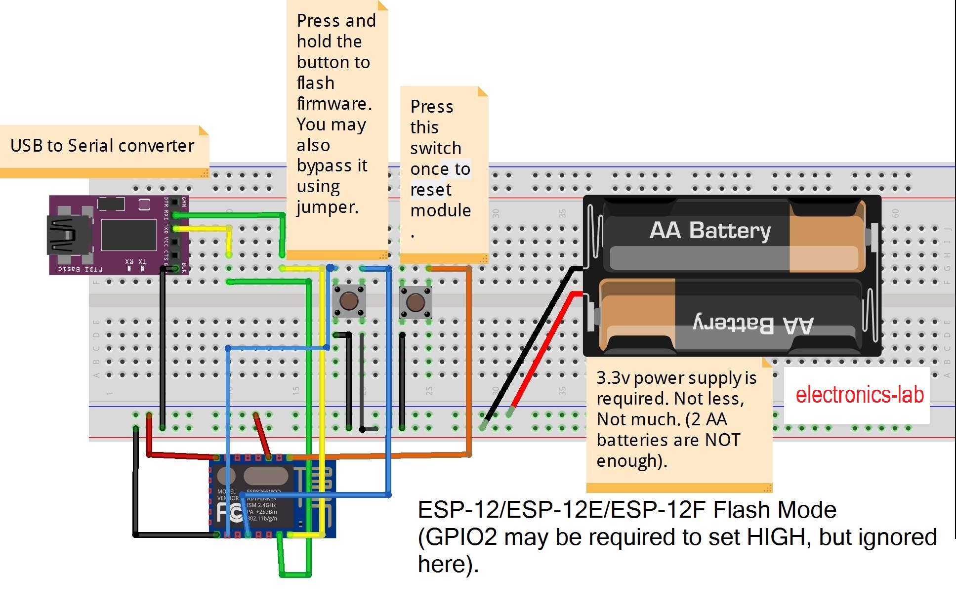
ESP-12(E/F):
- Connect GPIO0 to Ground (set it LOW or 0)
- Connect GPIO15 to Ground (set it LOW OR 0)
- Connect GPIO2 to Vcc (set it HIGH or 1)
- Connect CH_PD toVcc (set it HIGH or 1)
Pin Vcc and GND should be connected to power supply’s +VE and -VE rail respectively. TX and RX of ESP8266 should be connected to RX and TX of USB to TTL converter respectively.
Conclusion
You are done! Now just select your ESP8266 board from Tools > Board menu, write any program, and click on Upload button. The ESP8266 will run as standalone microcontroller now.
To have a clear idea, read the article FLASH AT FIRMWARE TO ESP8266 also.


