Vintage VQB 71 Seven-Segment LED Displays Make GPS Clock Both Brilliant and Attractive.
Stephen Holdaway recently announced his project, a beautiful vintage VQB71 7-segment display based GPS Clock. Inspired by the fantastic appearance of the LEDs, Holdaway explains that the clock was built with a handful of vintage VQB 71 seven-segment LED displays and an u-box NEO-6M GPS module.
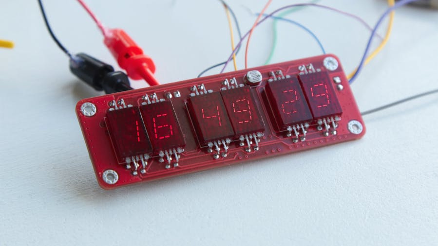
Stephen Holdaway recently announced his project, a beautiful vintage VQB71 7-segment display based GPS Clock.
Inspired by the fantastic appearance of the LEDs, Holdaway explains that the clock was built with a handful of vintage VQB 71 seven-segment LED displays and an u-box NEO-6M GPS module. “There are only so many applications for a 7-segment display these days, and I’m a firm believer that one person can never have enough clocks. A miniature version of the GPS Wall Clock for a desk seemed like a nice way to put these vintage digits on display”.
“A year ago, I picked up some new-old-stock “VQB 71” 7-segment displays – not for any particular project, but simply because they looked fantastic. These gorgeous, vintage common-anode digits have distinctive segments with six-tiny LEDs each, internally connected with bond-wires and encapsulated in transparent red epoxy/resin,” explains the ultra-compact GPS-driven clock designer, Stephen.
Compared to earlier designs, the GPS-driven clock was built with better functionalities in mind: better display accuracy, more buttons, less pin-sharing, GPS module configuration, etc. It replaces the ATMega88PA with a physically smaller but comparable 8-BIT STM8S003F3P6 microcontroller and integrates the GPS module into the layout instead of a separate breakout board. Offsets are also configured in the GPS module to explain electrical and processing delays in its display.
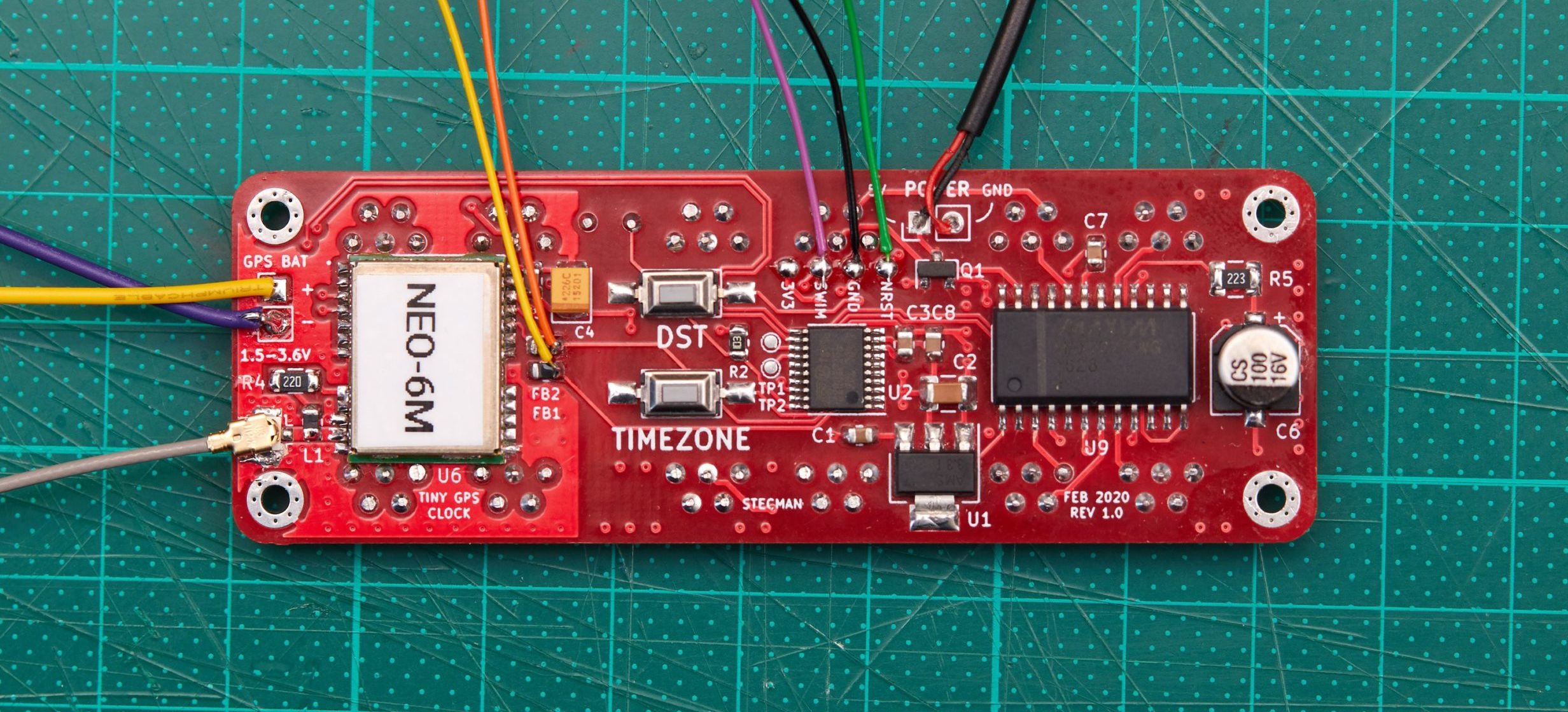
According to him, the module comes with an attached back-up battery to handle possible cold starts when briefly removing power. The power input is 5V with simple polarity protection and can be regulated to 3.3V for the STM8 and GPS module.
“To get the clock up and running quickly, I ported the code from the original AVR project to run on the STM8. This only required swapping out a few registers and pin mappings, replacing the SPI, UART, and ADC implementations, and adding mapping to set BCD values on the common-anode wiring of the MAX72XX. The board went to fab Mid-February, was manufactured over the course of 10days, and took a further 10 days to get to my bench in New Zealand”
Even though the clock is set and ready for use, Holdaway still plans on working more on the build’s firmware within the next few weeks. Full details of this project alongside its KICAD project file and schematics can be found on the project page, here.


