TinyUPS – Uninterruptible Power Supply based on ATtiny13A
Power interruption has a lot of side effects on projects. Especially projects with heavy processing requirements, it could corrupt the memory of the microprocessor/microcontroller, or lead to significant damage to other parts of the device.
Power interruption has a lot of side effects on projects. Especially projects with heavy processing requirements, it could corrupt the memory of the microprocessor/microcontroller, or lead to significant damage to other parts of the device. To mitigate this, several UPS solutions have been built, especially by folks in the Raspberry Pi community and as a contribution to this efforts, Wagiminator recently shared his designs for a UPS which is called TinyUPS.
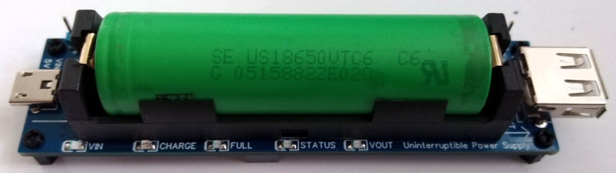
TinyUPS is a simple 5V/2.5A uninterruptible power supply with a li-ion battery as a buffer, a load sharing power path management system, and an ATtiny13 which; monitors the power supply for availability, the battery level for charge control, and shares battery information and power status with the device being powered. The device performs the basic functionality of keeping your device, alive for a when external power supply abruptly fails.
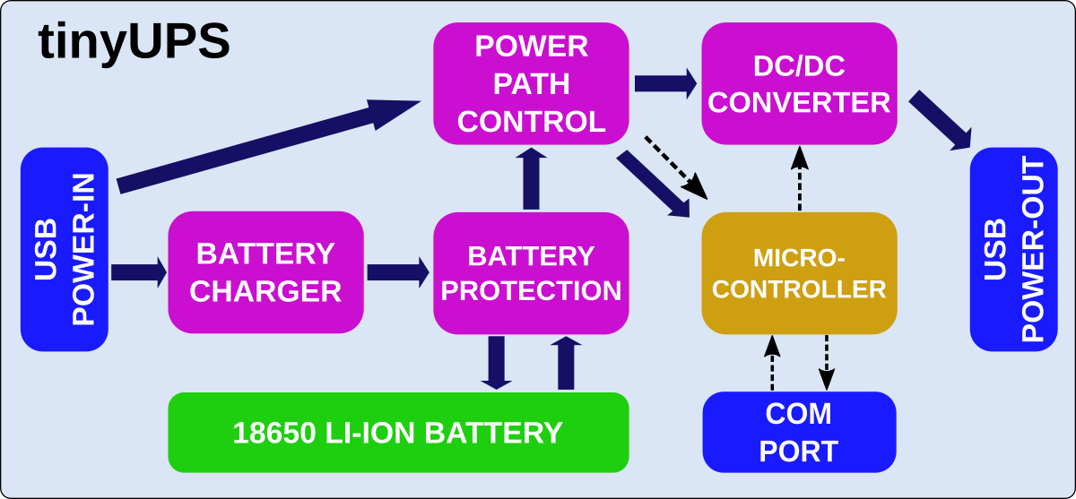
The operation principle of the tinyUPS is quite straight forward. When an external power supply is connected to the tiny ups, the input voltage or VCC of the ATtiny13 is delivered to the device and when the external power supply is not available, the load is supplied by the battery. As the battery begins to run out, monitored by the ATtiny13, it tells the device it is time to shut down by pulling a pin dedicated as a shutdown pin, LOW. The developer of the device being powered is expected to read this pin from time to time and initiate the shutdown process for the device when the pin goes LOW. After pulling the shutdown pin LOW, the tinyUPS waits for a few minutes (SHUTDOWN TIMER) to allow the connected device to safely shut down, after which the ATtiny13 deactivates the boost converter and turns off the power to the connected device. If the input voltage rises again (as a result of external power source being available), above a certain threshold (POWERONLEVEL) voltage, the tinyUPS comes on, activates the boost converter, and turns on power to the connected device.
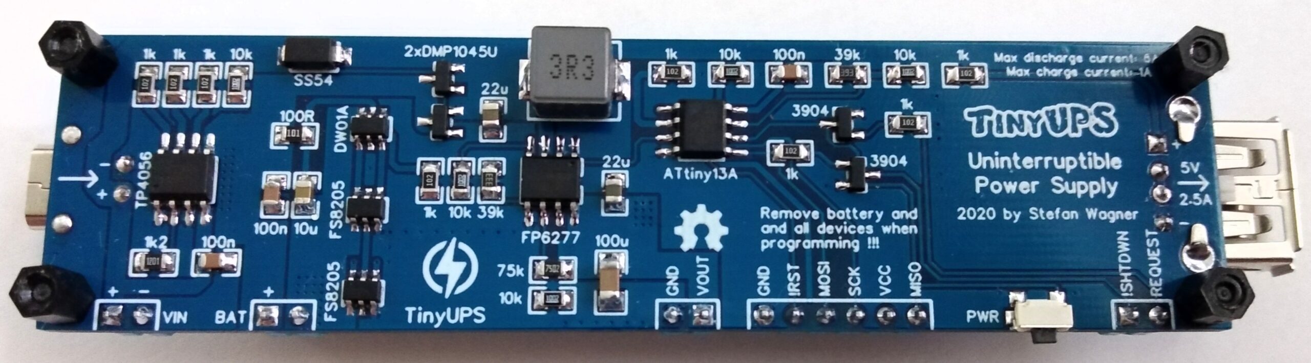
The UPS has been tested for various performance indicators including power efficiency and the results as documented by Wagiminator are stellar. Few requirements by the device for top performance however include that the external power supply to be used be capable of delivering enough power to charge the battery and to power the device connected to the UPS simultaneously. The maximum battery charging current is set to 1000mA but you can set a lower limit by selecting a different value of R3. The output voltage of the external power supply must not exceed 5.2V! and selecting a good 18650 with low internal resistance would be of high advantage.
A summary of some of the device’s power specification is provided below.
| Parameter | Value |
|---|---|
| Input Voltage | 4.5 – 5.2 V |
| Output Voltage | 4.8 – 5.2 V |
| Output Current | Max 2.5 A |
| Charging Current | Max 1000 mA |
| Standby Current | 95 uA |
Wagiminator has been kind enough to make the entire project open source, and all files from firmware to schematics and PCB layout are available on the project’s Github page. The page also contains a readme file that gives a broader explanation into the features embedded into the device.


