Use a Comparator or Op-Amp to Simplify Light Dependent Resistor Output
If your project calls for light sensitivity, it’s hard to beat light dependent resistors (LDRs), also known as photoresistors. They’re available for a few cents each, and their resistance varies based on how much light they receive.
If your project calls for light sensitivity, it’s hard to beat light dependent resistors (LDRs), also known as photoresistors. They’re available for a few cents each, and their resistance varies based on how much light they receive. In the dark, these devices produce resistances in the megohm range, and can fall to hundreds of ohms or even less when exposed to sufficient light. You first instinct when prototyping this type of device is likely to use an analog input on an Arduino or similar dev board to sense voltage levels. This works quite well in many situations, but you may also want to consider a comparator or operational amplifier (op-amp) to turn this analog input into a simple on/off signal. You could also use one of these components by itself to produce a usable output without the use of a microcontroller.
LDR Analog Input to Microcontroller
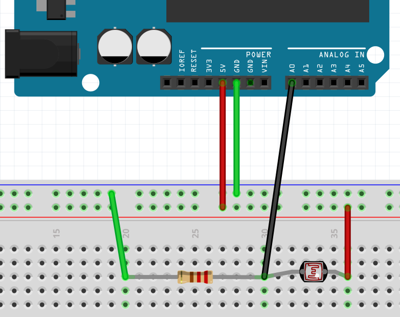
First, let’s examine how a microcontroller would see an LDR input. Using the circuit illustrated in the figure above with an Arduino Uno, an LDR is attached to 5VDC, then routed to the analog input A0. Voltage at the intersection of A0, the resistor, and LDR is divided between the fixed resistor and LDR, which decreases its resistance as light is applied. Voltage at this analog input increases with the lowered resistance in proportion to the amount of light the LDR sees.
The Arduino board is thus able to sense the resulting voltage level and convert it to an analog value. A threshold can be setup to respond to different light levels as on or off, or the analog signal can be used for proportional control. Note that the resistor in this illustration is just a placeholder; it would need to be adjusted based on your LDR sensitivity. You can also use a trimming resistor to tweak output values as needed.
Comparator Digitizes Analog Signal
What if you need light input, but just want an on/off value? Analog inputs can handle this programmatically, but if you’re using an Arduino Uno you’re restricted to the 6 analog pins. There’s also the normally minor issue of additional program complexity. If you need more performance out of your setup, you could turn to a comparator, or operational amplifier (op-amp) set up to act as one, to convert this analog value into a simple on/off signal.
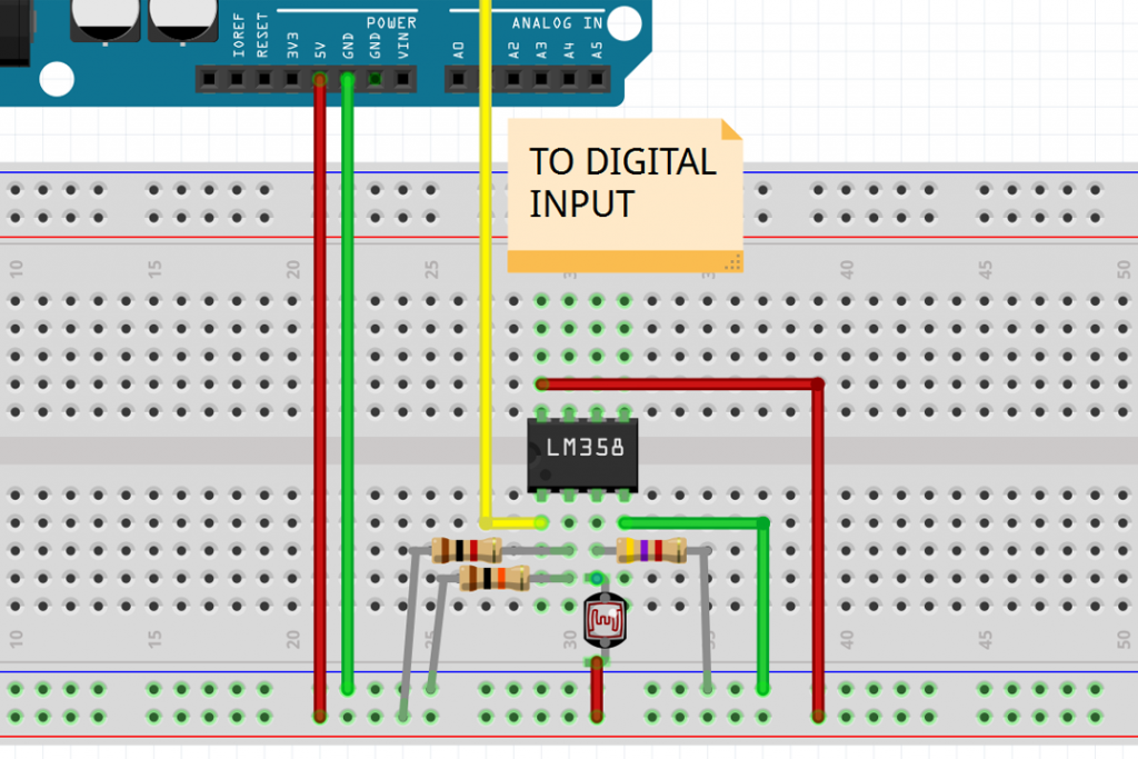
For example, if you were going to use an LM358 op-amp and LDR to detect light, you could tie the V+ (pin 8) to the 5V supply of your Arduino, ground (pin 4) to the Arduino’s ground, and output A (pin 1) to a digital pin on your Arduino board. The inverting input (pin 2) would be hooked to a voltage divider between +5V and ground, and your LDR would be setup in a voltage divider on the non-inverting input (pin 3). Here the LDR would act as the resistor from +5V to the op-amp input, and the set resistor would run to ground.
This will give you an on/off input to your Arduino without mucking about with any extra programming. Note that because of the way this op-amp operates, the output will be less than 5V, but will be sufficient to trigger the needed input. Obviously this will add some wiring complexity—more work than a few lines of code—so it’s not ideal in all situations.
Comparator Sans Arduino
You’re probably wondering at this point why you wouldn’t simply get a dev board capable of more analog inputs if that’s what is needed. After all, hooking up additional wiring or adding more complication to your PCB isn’t trivial. Certainly there are some applications that call for this, but for really simple electronics, you may not need a microcontroller at all.
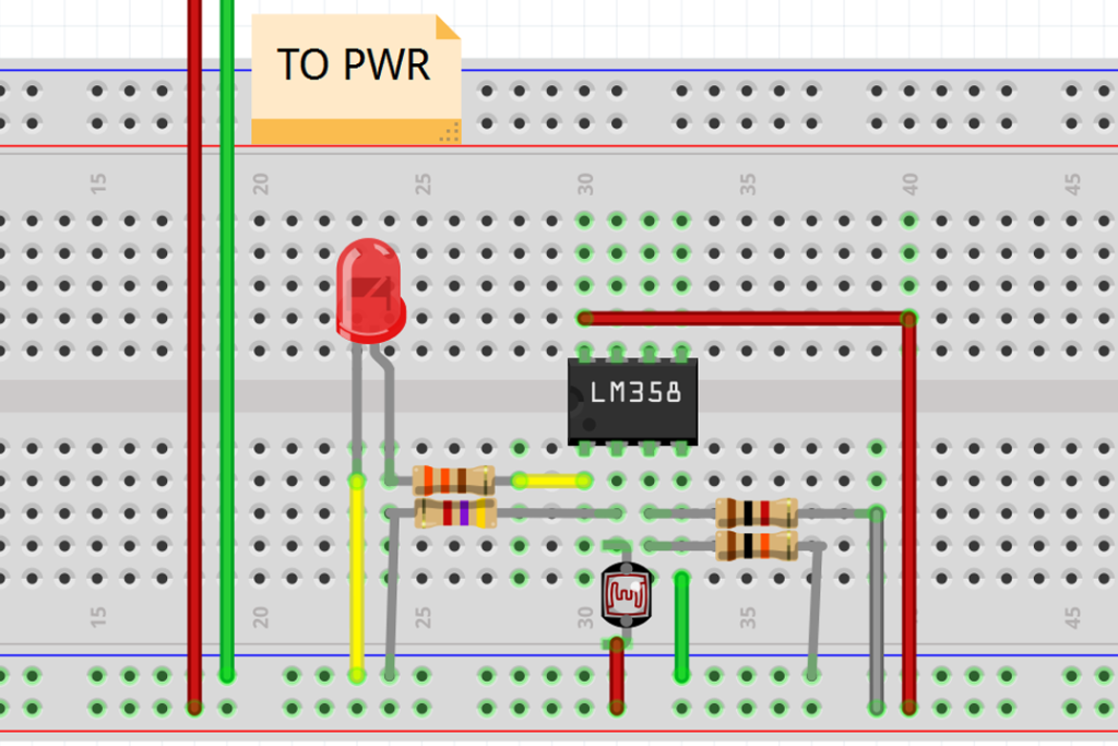
Illustration: Jeremy S. Cook in Fritzing
One such simple application would be a light that you want to come on when the ambient light drops below a certain threshold. In this application, you’d want to put the resistors only voltage divider on the non-inverting input (pin 3), while the LDR voltage divider would be placed on the inverting input (pin 2). This would cause the voltage on pin 2 to be larger than pin 3 when the light is on, turning the output (pin 1) on when there isn’t enough light.
Of course LDRs are but one type of sensor, and there are many models of op-amps and comparators with different characteristics available depending on your needs. If you’re just starting out with sensors and electronics, using a dev board like an Arduino is a great choice. As you advance in your knowledge, you might also consider analog electronics for your builds. While not appropriate or necessary for every project, it’s a great tool to have available when purely digital processing doesn’t quite fit your application.
Jeremy S. Cook and Zach Wendt are engineers who enjoy sharing how electronic components can best impact applications. Jeremy writes for a variety of technical publications. Zach works for Arrow Electronics, a major supplier of Arduino products.


What a Great explanation ..Really enjoyed and understood.
Thanks a lot…!!!