Controlling a LED with ESP32-C3-DevKITM-1 Development Board using ESP-IDF
In this article, we will explore another onboard functionality of Espressif’s ESP32-C3-DevKITM-1 which is the onboard RGB LED. With its powerful connectivity, compact size at such a low cost the ESP32-C3- DevKit M-1 board is a must-try for your next IoT project.
In this article, we will explore another onboard functionality of Espressif’s ESP32-C3-DevKITM-1 which is the onboard RGB LED. With its powerful connectivity, compact size at such a low cost the ESP32-C3- DevKit M-1 board is a must-try for your next IoT project. You can read the official documentation of the development board as well.
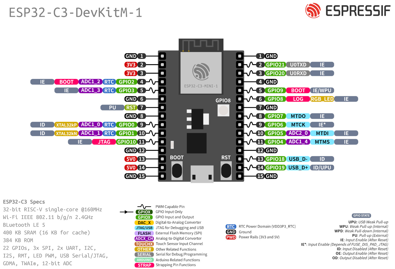
The board features an onboard addressable RGB LED (WS2812), driven by GPIO8 which can be configured to glow in different colors based on the RGB value of the color given. ESP-IDF being the native software development framework for ESP boards with all API, Toolchain scripts are preinstalled. In this article, we focus on the programming of ESP32-C3 using ESP-IDF.
We will program the ESP32-C3-DevKITM-1 module for the following blink applications:
- Single Blink Example
- LED color and pattern
- Led control on Input
- External LED blink
Let’s see all these one by one:
1. Single Blink LED Use Case on ESP32-C3-DevKITM-1
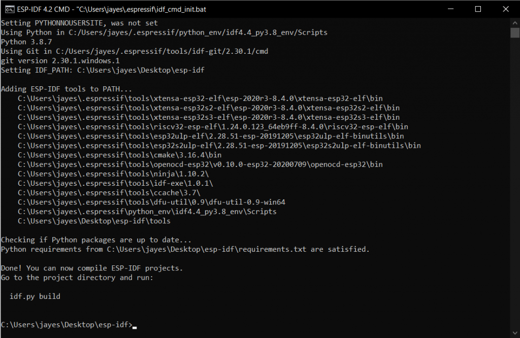
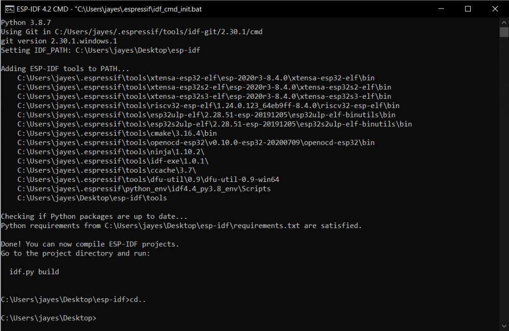
Step1: Launch your ESP-IDF CMD Application.
Step2: By default, you will be in the esp-idf home directory, change the directory by using cd.. command.
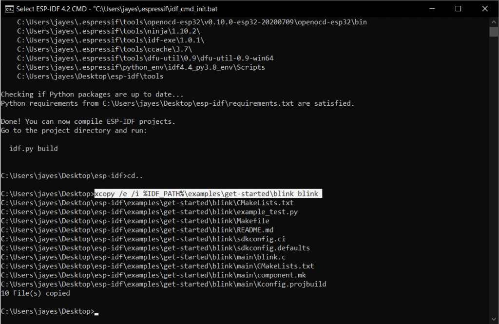
Step3: Use xcopy /e /i %IDF_PATH%\examples\get-started\blink blink command. This makes a copy of the blinking folder situated in the examples folder of the esp-idf home directory in the current location.
Step4: Switch to the newly created folder using the cd blink command.
Step5: Execute idf.py set-target and idf.py menuconfig commands to make the program compatible with the board you have.

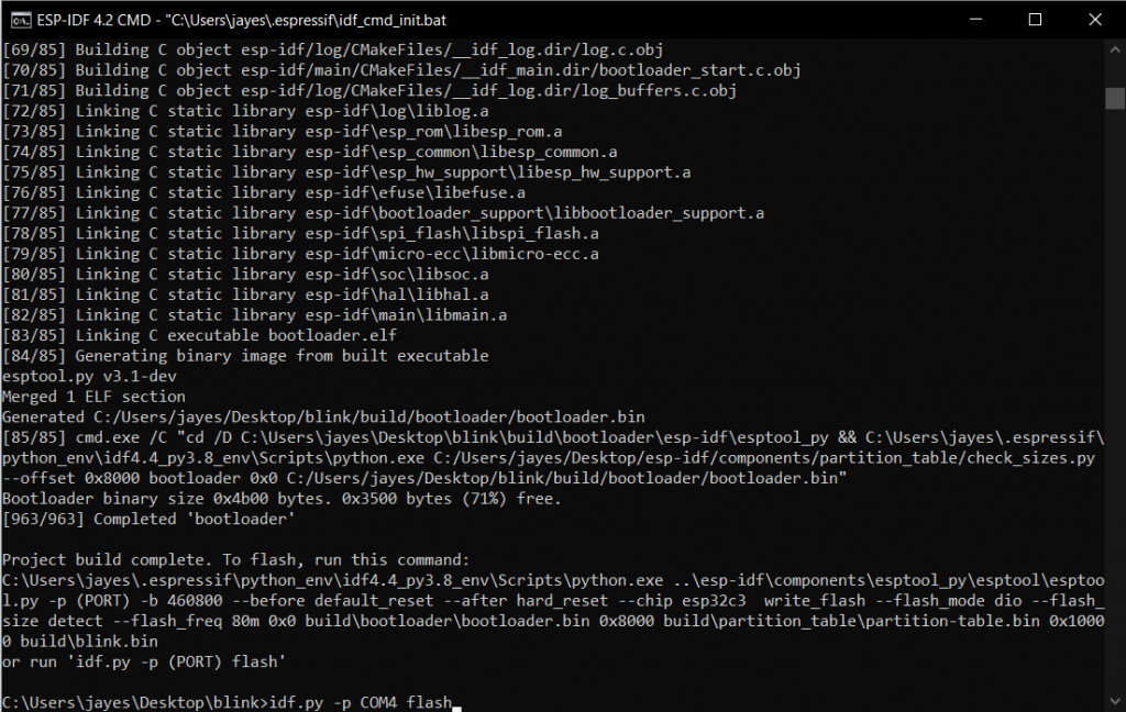
Step6: Now build the program using the idf.py build command.
Step7: Connect your esp board now and flash the program using idf.py -p (PORT) flash. Here (PORT) is the Port at which your board is connected. This can be found using the device manager on your PC.
Once the flashing is complete, you’ll get a Done message as shown below.
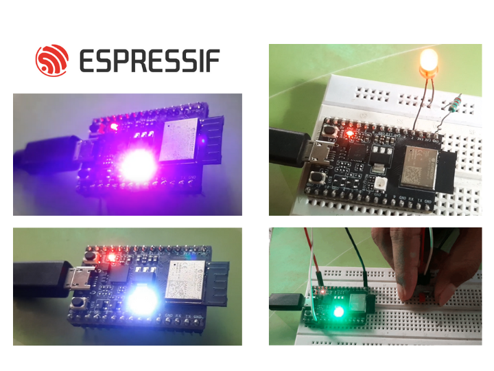
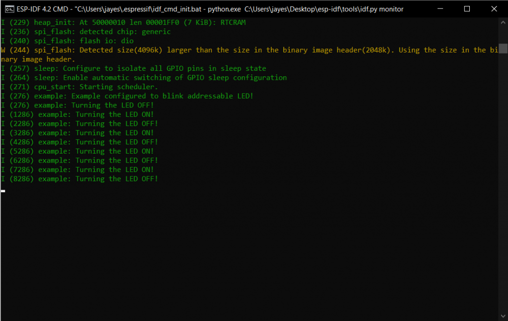
Now, your Onboard LED of the ESP32 C3 board should start blinking white. The Idf.py monitor command gives the real-time status of the LED from the board.
2. LED Colour and Pattern on ESP32-C3-DevKITM-1
As our ESP32 C3 DevKITM-1 board has an RGB LED, we’ll now see how to configure it to the desired color. In order to do so, follow Step3 of the previous single blink example.
Step4: Now, navigate to the newly created blink folder in file explorer. Here, in our case, the new blink folder was made on the Desktop.

Step5: Open blink -> main -> blink.c file in any suitable application as per your preference. Here, we used the Notepad application to open and edit the blink.c file.
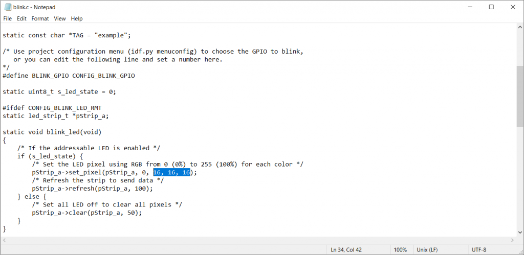
As instructed from the given comments, the highlighted values in the above figure are the RGB values of the glowing LED. Set these values as required, to obtain your desired color as the output. We set these values to 255, 0, 255 to obtain Magenta Colour. Save the file.
Step6: Come back now to your ESP-IDF CMD Application and execute step4 to step7 of the previous single blink example. Now, your Onboard LED of the ESP32 C3 board should start blinking magenta and can be monitored by the Idf.py monitor command.
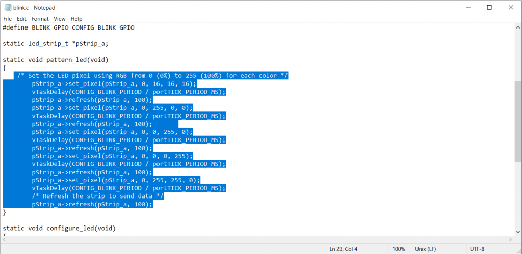
The same logic was followed in order to write a program to make the onboard LED glow in a color pattern.
Code LED pattern
/* LED Pattern Example
Makes the Onboard LED of ESP32-C3-DevKITM-1 glow in colour pattern from White -> Red -> Green -> Blue -> Yellow
*/
#include <stdio.h>
#include "freertos/FreeRTOS.h"
#include "freertos/task.h"
#include "driver/gpio.h"
#include "esp_log.h"
#include "led_strip.h"
#include "sdkconfig.h"

#define BLINK_GPIO CONFIG_BLINK_GPIO
static led_strip_t *pStrip_a;

static void pattern_led(void)
{
/* Set the LED pixel using RGB from 0 (0%) to 255 (100%) for each color */
pStrip_a->set_pixel(pStrip_a, 0, 16, 16, 16);
vTaskDelay(CONFIG_BLINK_PERIOD / portTICK_PERIOD_MS);
pStrip_a->refresh(pStrip_a, 100);
pStrip_a->set_pixel(pStrip_a, 0, 255, 0, 0);
vTaskDelay(CONFIG_BLINK_PERIOD / portTICK_PERIOD_MS);
pStrip_a->refresh(pStrip_a, 100);
pStrip_a->set_pixel(pStrip_a, 0, 0, 255, 0);
vTaskDelay(CONFIG_BLINK_PERIOD / portTICK_PERIOD_MS);
pStrip_a->refresh(pStrip_a, 100);
pStrip_a->set_pixel(pStrip_a, 0, 0, 0, 255);
vTaskDelay(CONFIG_BLINK_PERIOD / portTICK_PERIOD_MS);
pStrip_a->refresh(pStrip_a, 100);
pStrip_a->set_pixel(pStrip_a, 0, 255, 255, 0);
vTaskDelay(CONFIG_BLINK_PERIOD / portTICK_PERIOD_MS);
/* Refresh the strip to send data */
pStrip_a->refresh(pStrip_a, 100);
}
static void configure_led(void)
{
/* LED strip initialization with the GPIO and pixels number*/
pStrip_a = led_strip_init(CONFIG_BLINK_LED_RMT_CHANNEL, BLINK_GPIO, 1);
/* Set all LED off to clear all pixels */
pStrip_a->clear(pStrip_a, 50);
}
void app_main(void)
{
/* Configure the peripheral according to the LED type */
configure_led();

while (1) {
printf(" LED Pattern!");
pattern_led();
vTaskDelay(CONFIG_BLINK_PERIOD / portTICK_PERIOD_MS);
}
}
The Led now glows from White -> Red -> Green -> Blue -> Yellow as seen from the video.
The delays for the pattern or even for the blink examples can be set from the vTaskDelay() lines.
For example, setting these delays provides us with the following output.
3. Controlling Onboard LED of ESP32-C3-DevKITM-1 Using External Switch
This example is basically a combination of Single blink and LED pattern examples. The board will choose from either of these examples based on an external input switch. An if-else structure is implemented here.
Components:
- ESP32-C3-DevKitM-1
- Breadboard
- Switch (button)
- Jumper cables
- USB 2.0 cable
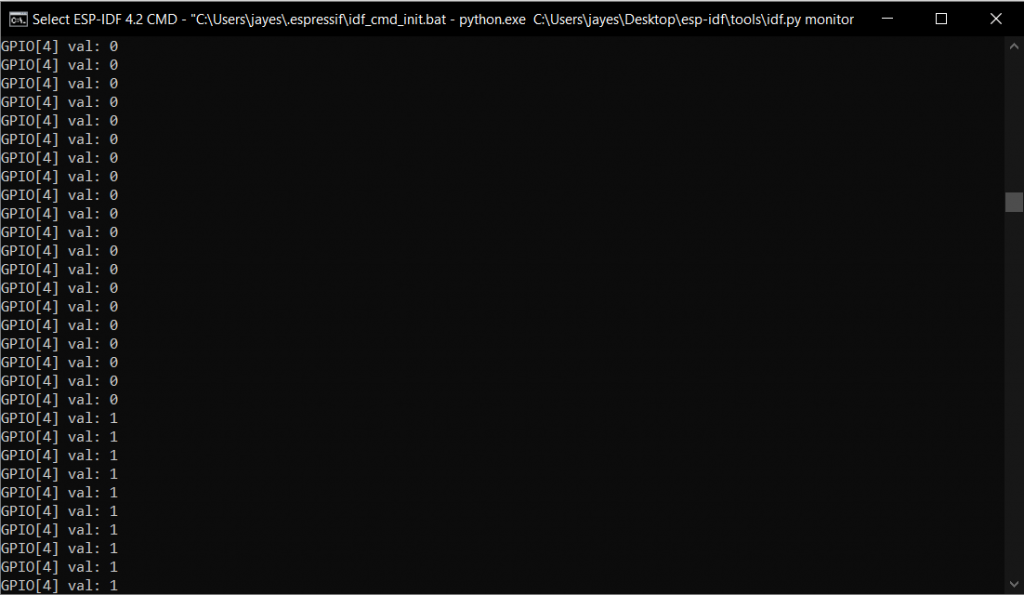
As and when the input on pin 4 of the ESP32-C3-DevKitM-1 board becomes high (1), the LED color pattern example is executed, and else i.e. on low input (0), the Single blink example is executed.
Code can be found below:
#include <stdio.h>
#include "freertos/FreeRTOS.h"
#include "freertos/task.h"
#include "driver/gpio.h"
#include "esp_log.h"
#include "led_strip.h"
#include "sdkconfig.h"

static const char *TAG = "example";
/* Use project configuration menu (idf.py menuconfig) to choose the GPIO to blink,
or you can edit the following line and set a number here.
*/

#define BLINK_GPIO CONFIG_BLINK_GPIO
#define LED 18
#define IN 1
static uint8_t s_led_state = 0;
static int input=0;
static led_strip_t *pStrip_a;

static void blink_led1(void)
{
if (s_led_state) {
/* Set the LED pixel using RGB from 0 (0%) to 255 (100%) for each color */
pStrip_a->set_pixel(pStrip_a, 0, 16, 16, 16);
/* Refresh the strip to send data */
pStrip_a->refresh(pStrip_a, 100);
} else {
/* Set all LED off to clear all pixels */
pStrip_a->clear(pStrip_a, 50);
}
s_led_state=!s_led_state;
}

static void blink_led2(void)
{
{
/* Set the LED pixel using RGB from 0 (0%) to 255 (100%) for each color */
pStrip_a->set_pixel(pStrip_a, 0, 16, 16, 16);
vTaskDelay(CONFIG_BLINK_PERIOD / portTICK_PERIOD_MS);
pStrip_a->refresh(pStrip_a, 100);
pStrip_a->set_pixel(pStrip_a, 0, 200, 16, 16);
vTaskDelay(CONFIG_BLINK_PERIOD / portTICK_PERIOD_MS);
pStrip_a->refresh(pStrip_a, 100);
pStrip_a->set_pixel(pStrip_a, 0, 16, 200, 16);
vTaskDelay(CONFIG_BLINK_PERIOD / portTICK_PERIOD_MS);
pStrip_a->refresh(pStrip_a, 100);
pStrip_a->set_pixel(pStrip_a, 0, 16, 16, 200);
vTaskDelay(CONFIG_BLINK_PERIOD / portTICK_PERIOD_MS);
pStrip_a->refresh(pStrip_a, 100);
pStrip_a->set_pixel(pStrip_a, 0, 200, 200, 16);
vTaskDelay(CONFIG_BLINK_PERIOD / portTICK_PERIOD_MS);
/* Refresh the strip to send data */
pStrip_a->refresh(pStrip_a, 100);
}
}
static void configure_led(void)
{
ESP_LOGI(TAG, "Example configured to blink addressable LED!");
/* LED strip initialization with the GPIO and pixels number*/
pStrip_a = led_strip_init(CONFIG_BLINK_LED_RMT_CHANNEL, BLINK_GPIO, 1);
/* Set all LED off to clear all pixels */
pStrip_a->clear(pStrip_a, 50);
gpio_set_direction(LED, GPIO_MODE_OUTPUT);
gpio_set_direction(IN, GPIO_MODE_INPUT);
}


void app_main(void)
{

/* Configure the peripheral according to the LED type */
configure_led();

while (1) {

input=gpio_get_level(4);
printf("GPIO[%d] val: %d\n", 4, input);
if(input==0){
blink_led1();
gpio_set_level(LED, s_led_state);
vTaskDelay(500/ portTICK_PERIOD_MS);
}
else{
blink_led2();
gpio_set_level(LED, s_led_state);
vTaskDelay(500/ portTICK_PERIOD_MS);
}
}
}
4. External LED Blink Use Case on ESP32-C3-DevKITM-1
Apart from the onboard RGB led, we can also set an externally connected led to blink. Here, the external LED is connected to pin 2 of the ESP32-C3-DevKitM-1 board.
Components:
- ESP32-C3-DevKitM-1
- Breadboard
- LED
- A series resistor ( 220 Ω)
- Jumper cables
- USB 2.0 cable
The Code can be found below:
/* External LED Blink
Blink Example configured to blink GPIO LED
*/
#include <stdio.h>
#include "freertos/FreeRTOS.h"
#include "freertos/task.h"
#include "driver/gpio.h"
#include "esp_log.h"
#include "led_strip.h"
#include "sdkconfig.h"

static const char *TAG = "example";

/* Use project configuration menu (idf.py menuconfig) to choose the GPIO to blink,
or you can edit the following line and set a number here.
*/
#define BLINK_GPIO 2

static uint8_t s_led_state = 0;

static void blink_led(void)
{
/* Set the GPIO level according to the state (LOW or HIGH)*/
gpio_set_level(BLINK_GPIO, s_led_state);
}

static void configure_led(void)
{
ESP_LOGI(TAG, "Example configured to blink GPIO LED!");
gpio_reset_pin(BLINK_GPIO);
/* Set the GPIO as a push/pull output */
gpio_set_direction(BLINK_GPIO, GPIO_MODE_OUTPUT);
}


void app_main(void)
{

/* Configure the peripheral according to the LED type */
configure_led();

while (1) {
ESP_LOGI(TAG, "Turning the LED %s!", s_led_state == true ? "ON" : "OFF");
blink_led();
/* Toggle the LED state */
s_led_state = !s_led_state;
vTaskDelay(CONFIG_BLINK_PERIOD / portTICK_PERIOD_MS);
}
}
If you are new to the ESP32-C3-DevKITM-1 development board, you can visit the following articles to get a better understanding of it.