The EasyEDA get updated to the EasyEDA PRO version which has 3D Design Function!
As you may know, EasyEDA is updated to the EasyEDA Pro version months ago, and there are lots of functions that get upgraded or build up. Today we will focus on the 3D design function and introduce how to use it.
As you may know, EasyEDA is updated to the EasyEDA Pro version months ago, and there are lots of functions that get upgraded or build up. Today we will focus on the 3D design function and introduce how to use it.
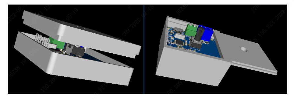
EasyEDA Pro supports the design of simple 3D housings, allowing users to quickly draw and build simple housings.
If the simple 3D housing designed in EasyEDA Pro does not meet your needs, you can export the 3D housing with the option to export it in STEP or OBJ format for further design in other professional 3D design tools.
Step 1
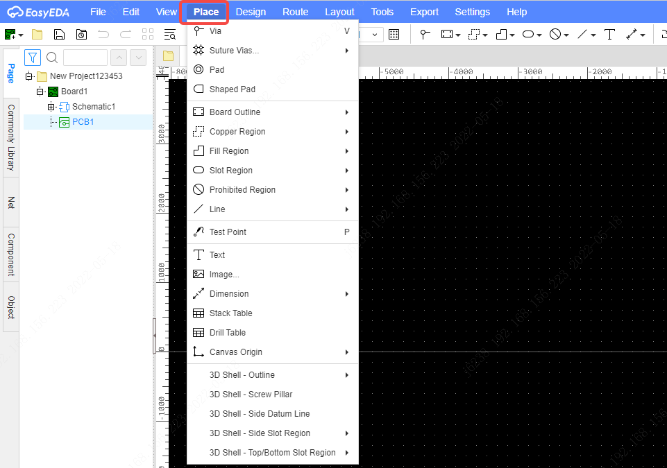
To design a 3D housing, the edges of the 3D housing need to be drawn first.
Entry: Menu – Place – 3D Shell – Outline.
Step 2
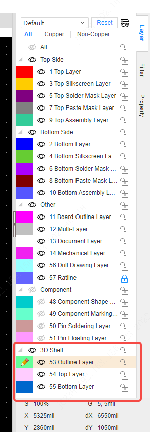
The drawn element is automatically switched to the 3D shell outline layer.
Step 3
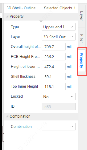
By clicking on the “3D Shell – outline” element you can set its properties in the properties panel on the right.
Step4
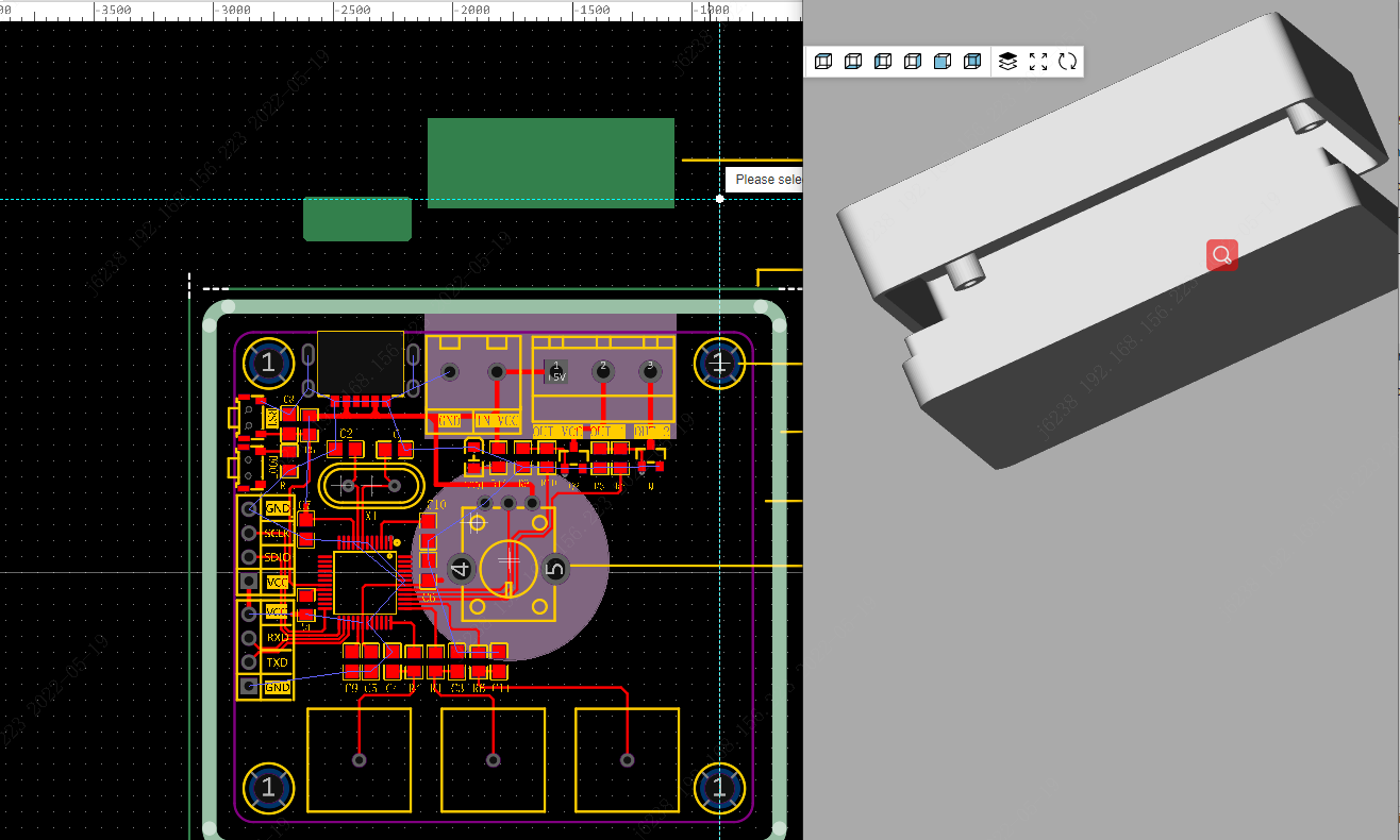
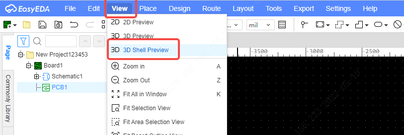
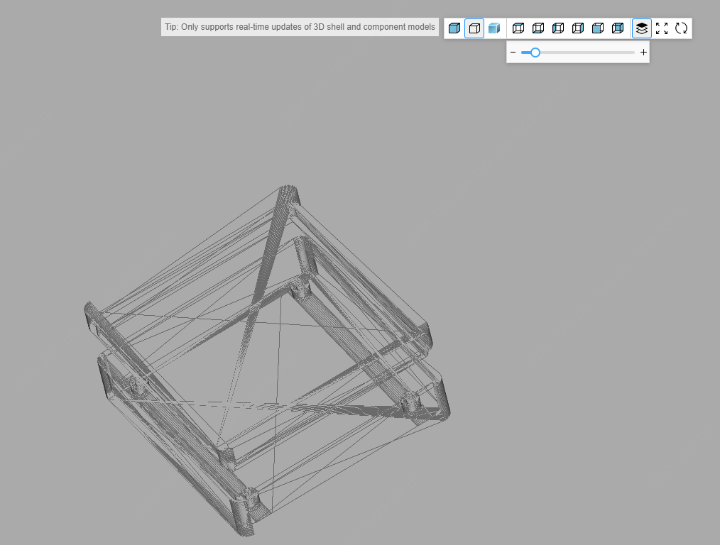
After drawing, a simultaneous preview is available in the Top menu – View – 3D shell preview, where the parameters related to the 3D shell modified by the PCB are synchronized and updated inside the 3D preview. 3D shell preview opens in a new separate window.
Step5
Description of properties.
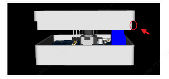
Type: top and bottom shell, push cover. EasyEDA Pro offers two shell types, for the time being, only the rectangular shell supports push covers.
Properties
- Layers: as with other lines, you can switch to other layers, and the type changes accordingly when the layer is switched.
- Overall height of shell: Overall height of the shell, e.g. when the upper and lower shells are combined
- Height of the lower shell: the height of the lower shell. The height of the upper shell is automatically calculated from the overall height.
- Shell Thickness: The thickness of the shell. It is recommended that it is greater than or equal to 1.5 mm, otherwise, it will break easily when manufactured in different materials and sizes.
- Top Inner Height: The height of the alignment recess in the inner wall of the upper shell
So, let’s see how it works!
Step 6
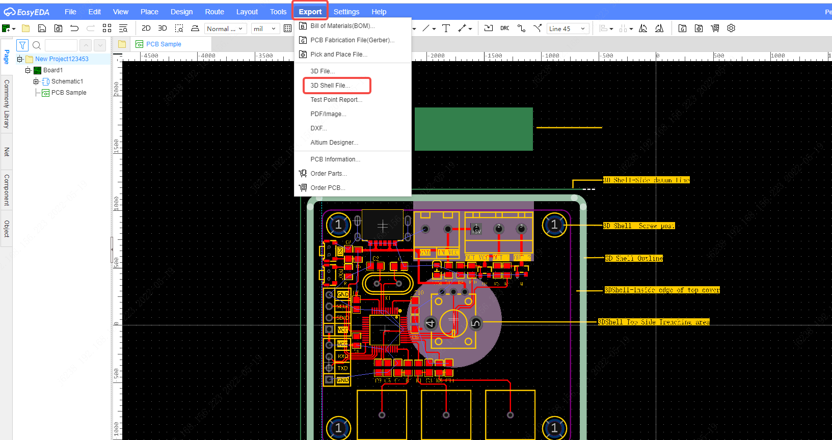
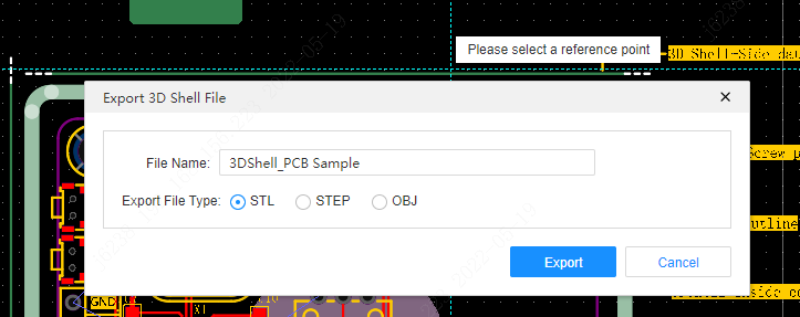
If it already meets your need, you can just output it into an STL file (there are 3 types of files you can output, stl, step, or obj)for manufacturing
Step 7
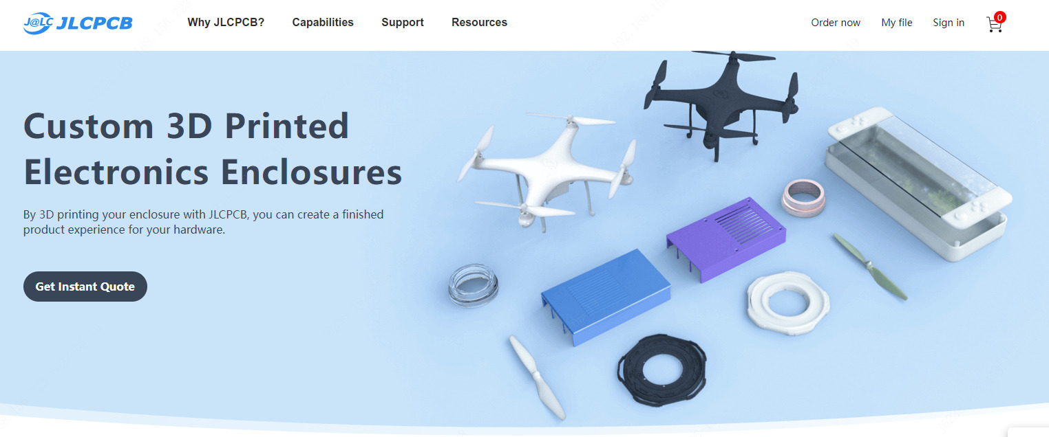
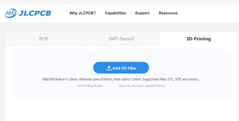
Manufacturing: Upload your STL file directly on the JLCPCB 3D Pringting service page, you will get an instant quote for it and it will be finished and delivered in around 2 days. Also, they have $54 Coupons for newly registered users now.
If there is anything in doubt, leave me a comment. For more interesting 3D printing design software, feel free to share with us.


