Programmable USB Hub has I2C, GPIO and SPI
A USB hub that's also a dev board and an I2C, GPIO, and SPI bridge In addition to being a 4-port USB 2 High-Speed hub, this Programmable USB hub is also: A CircuitPython based development board. A bridge between your computer and I2C (via Sparkfun Qwiic connectors), GPIO, and SPI (via its mikroBUS header).
In addition to being a 4-port USB 2 High-Speed hub, this Programmable USB hub is also:
- A CircuitPython based development board.
- A bridge between your computer and I2C (via Sparkfun Qwiic connectors), GPIO, and SPI (via its mikroBUS header).
- A power supply, providing 6 A of 5 V power to downstream devices and 13 mA resolution monitoring (per-port). Port power is individually limitable and switchable.
- A USB to TTL Serial adapter.
- A flexible embedded electronics test and development tool. USB data pairs are individually switchable, allowing you to emulate device removal and insertion via software.
- Mountable.
- Functionally flexible. Open source python drivers on the upstream host and Python firmware on the internal MCU allow the behavior of this USB hub to be easily changed to suit your application and environment.
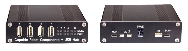
The Capable Robot Programmable USB hub is housed in a robust extruded aluminum enclosure.
Internally mounted LED light pipes direct status information from 10 RGB LEDs to the front panel for easy observation of hub state.
The rear of the enclosure exposes the upstream USB connection and a USB port to re-program and communicate with the internal MCU. Also exposed are two I2C buses (via Sparkfun Qwiic connectors), the Programmable USB hub’s UART, and 2x GPIO. Input power is provided to the hub by a locking Molex connector.
Features and Specifications
- USB2 High-Speed Hub
- 4x USB2 High Speed (480 mbps) downstream ports
- 1x USB2 High Speed (480 mbps) upstream port
- 5th endpoint on USB hub exposes I2C, SPI, UART, and 2x GPIO
- Data lines to each USB port can be disconnected via software commands. This allows errant USB devices to be “unplugged” virtually and re-enumerated.
- USB digital signals can be boosted to help drive long cables.
- Power Monitoring & Control
- 5 V power on each downstream port can be individually turned on and off
- Monitor the power consumed by each port at up to 200 Hz at a resolution of 13 mA
- Adjustable (per-port) current limits between 0.5 A and 2.6 A
- Onboard regulator supports 12 V to 24 V power input and generates 6 A of 5 V power for downstream USB devices; both voltages can be monitored by the internal MCU. No power is drawn from the upstream USB port.
- Input power is protected from over-voltage events and reverse-polarity connection.
- Physical IO
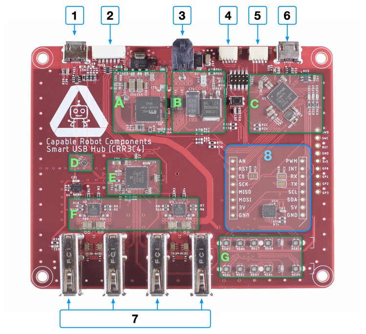
- mikroBUS header to add additional sensors and connectivity. Solder jumpers allow the UART and SPI pins to connect to either the USB hub or the MCU.
- JST GH connector with UART and 2x GPIO, controlled by the USB hub.
- 2x Sparkfun Qwiic connectors enable easy attachment of I2C sensors to the USB hub or to the internal MCU.
- 5x RGB status LEDs to visualize port power draw
- 5x RGB status LEDs to visualize port connection types
The project is live on Crowdsupply.com and has 49 days left with pledges starting at $200.


