ICP12 USBSTICK, A New Tool for Signals Control & Monitoring
iCircuit Technologies had produced the iCP12 usbStick, a mini size 28 pin USB PIC IO development board and a good tool for signal monitoring (as oscilloscope), data acquisition and circuit troubleshooting at 1mSec/Samples period. The iCP12 usbStick is a PIC18F2550 based USB development board that comes preloaded with Microchip’s USB HID bootloader which allows users to upload an application firmware directly through a PC’s USB port without any external programmer.
iCircuit Technologies had produced the iCP12 usbStick, a mini size 28 pin USB PIC IO development board and a good tool for signal monitoring (as oscilloscope), data acquisition and circuit troubleshooting at 1mSec/Samples period.
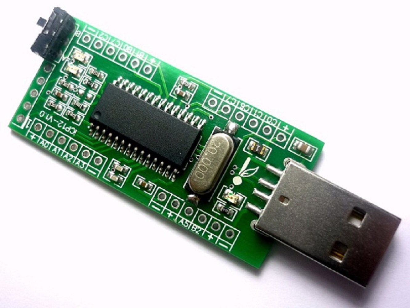
The iCP12 usbStick is a PIC18F2550 based USB development board that comes preloaded with Microchip’s USB HID bootloader which allows users to upload an application firmware directly through a PC’s USB port without any external programmer. It provides access to its I/O pins through 0.1″ pitch headers. A slide switch is also provided on board to select the operation of the board in Bootloader or Normal mode.
The features of iCP12 are listed as following:
- Mini size, easy interfacing, high performance and user friendly device
- Used with PIC18F2553 28-Pin Flash USB PIC MCU
- Excellent flexibility that allows user to expand the board with plug and play modules
- Peripheral Features:
- 13x IO Port (6x 12bit ADC pins, 2x 10 bit PWM/Freq/DAC pins)
- Serial port emulation (UART Baud Rates: 300 bps to 115.2 kbps)
- Supported operating systems (32bit/64bit): Windows XP ,Windows Vista, Windows 7, Windows 8, Windows 10, Linux, Mac OS X and Raspberry Pi
- Maximum Voltage: 5Vdc
- 100mA current output at VDD pin with over-current protection
- 20MHz oscillator
- Green LED – power on indicator
- 2x LEDs (Green, Red) – status indicator
- ICSP Connector – on-board PIC programming
- Switch Mode Selection – Boot or Normal mode
The iCP12 usbStick board is shipped with a preloaded data acquisition firmware that emulates as a virtual COM port to PC. Thereafter, the communication between the PC and usbStick is serial. The firmware also supports basic I/O control and data logging feature. They provide a PC application named SmartDAQ that is specially developed to communicate with the usbStick and control its I/O pins, PWM outputs, and record ADC inputs.
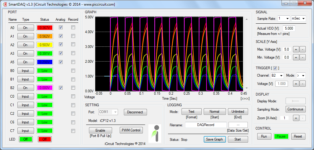
SmartDAQ has a very friendly GUI with real-time waveform displays for 6 analog input channels. The time and voltage axes scales are adjustable. SmartDAQ can log the ADC data in both text and graphic form concurrently. One can utilize this feature to construct a low-cost data acquisition system for monitoring multiple analog sensor outputs such as temperature, accelerometer, gyroscope, magnetic field sensor, etc.
SmartDAQ v1.3 Features:
- Sampling channel: 6x Analogs (12bits ADC/1mV Resolution) + 7x Digitals (Input/Output)
- Maximum Sampling rate: 1KHz or 1mSec/Samples
- Sampling voltage: 0V – 5V (scalable graph) at 5mV Resolution
- Sampling period:
- mSec: 1, 2, 5, 10, 20, 50, 100, 200, 500
- Sec: 1, 2, 5, 10, 20, 30
- Min: 1, 2, 5, 10, 20, 30, 60
- Trigger Mode: Larger [>], Smaller [<], Positive edge [↑], Negative edge [↓]
- Sampling Mode: Continuous, Single
- Logging Function:
- Save Format: Text, Graphic, Both
- Start Time: Normal, Once Trigger, 24-Hour Clock (Auto Run)
- End Time: Unlimited, Data Size, 24-Hour Clock (Auto Stop)
- Recorded Data format: Graphic | text | excel
iCP12 is available with the PIC18F2550 for $15, and with the PIC18F2553 for $24.5. You can order it through the official page where you can also get more details about iCP12 and its source files.
You can also see this product preview to know more about its functionality.


ICP12 USBSTICK is not a toy, it is a junk! Phase is fail 270 degre. The software too old and it is wrong.
Where is the new PC-software? I wanted to buy 10 pieces, but I dare not buy them.
What issue did you experience?