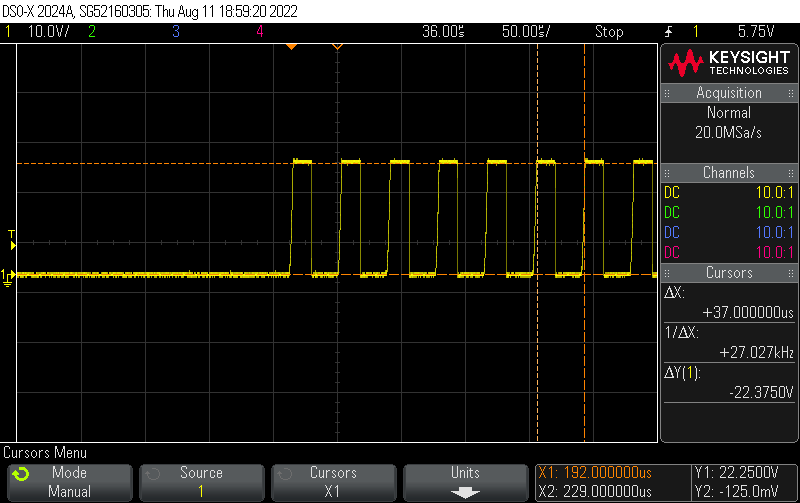
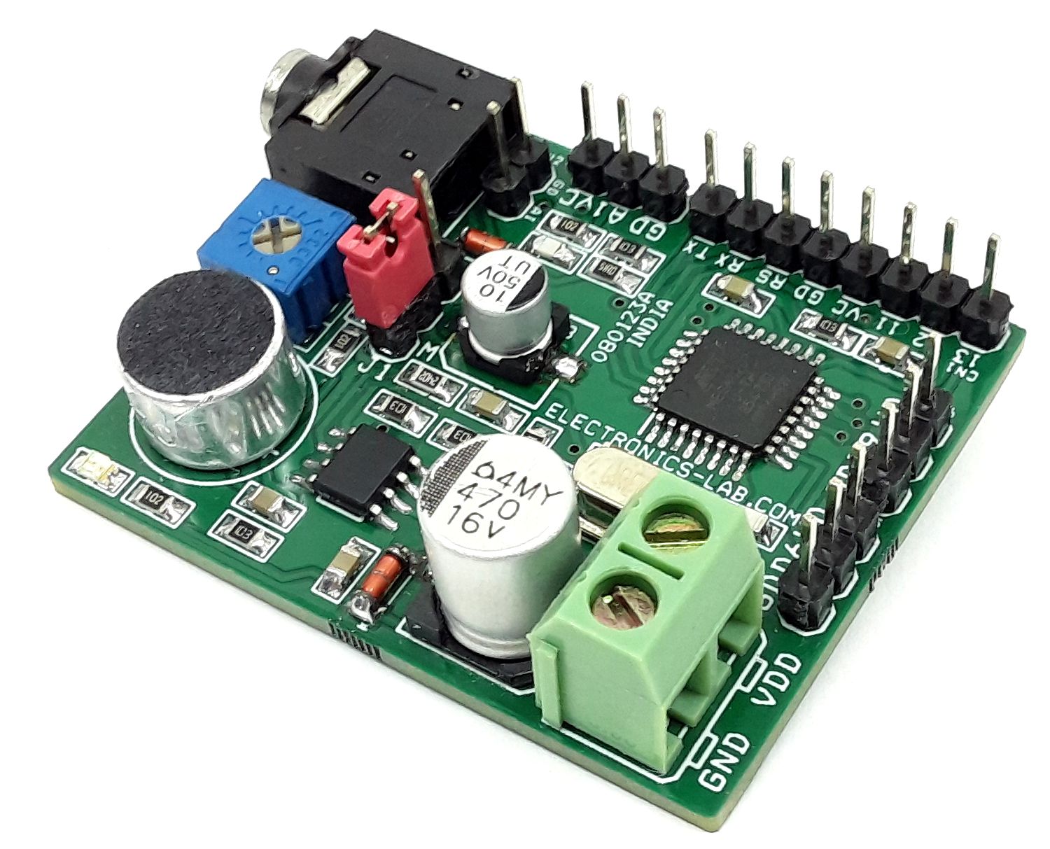
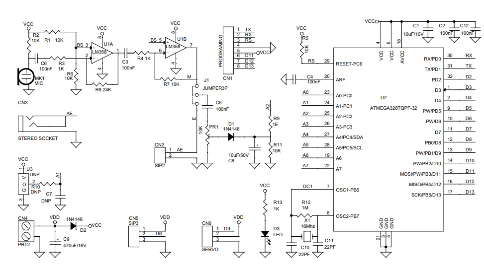
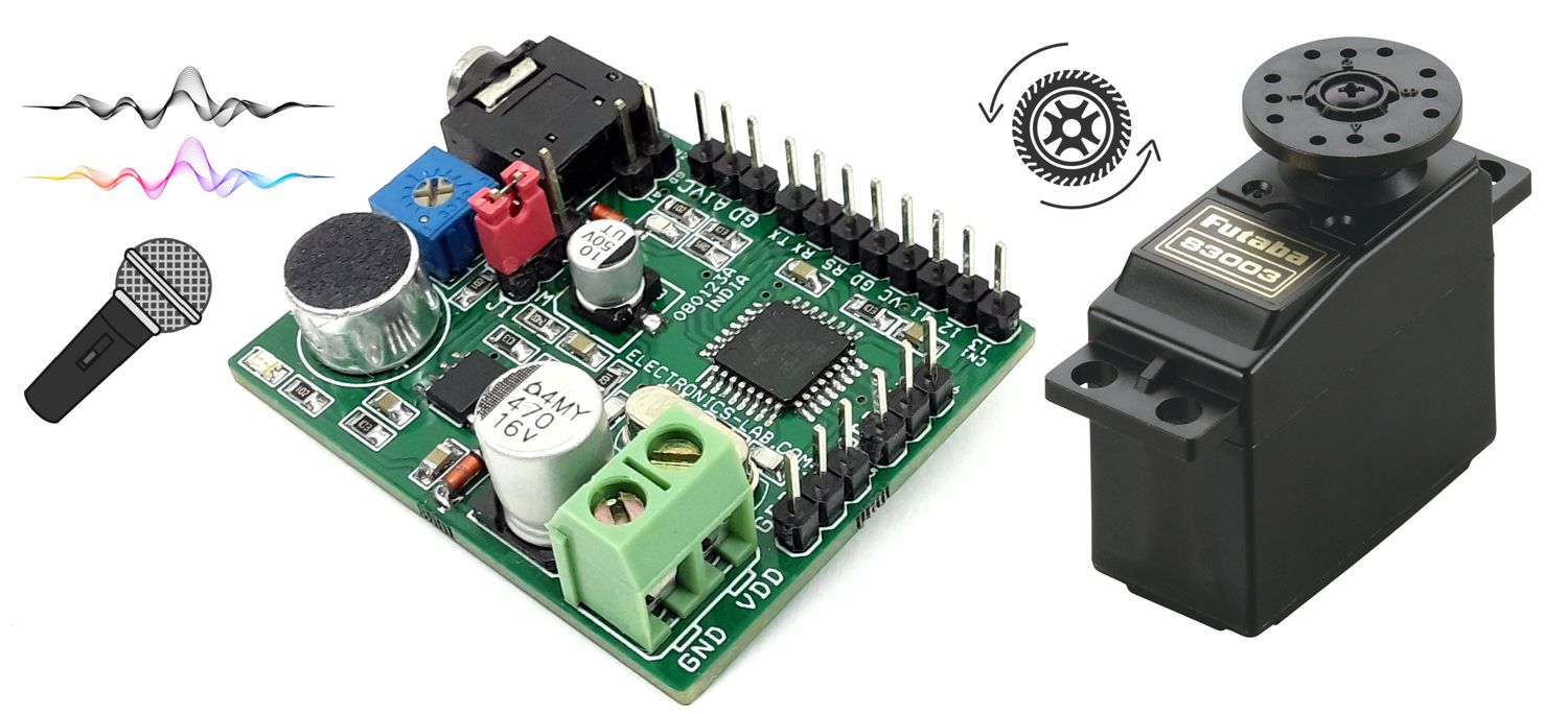
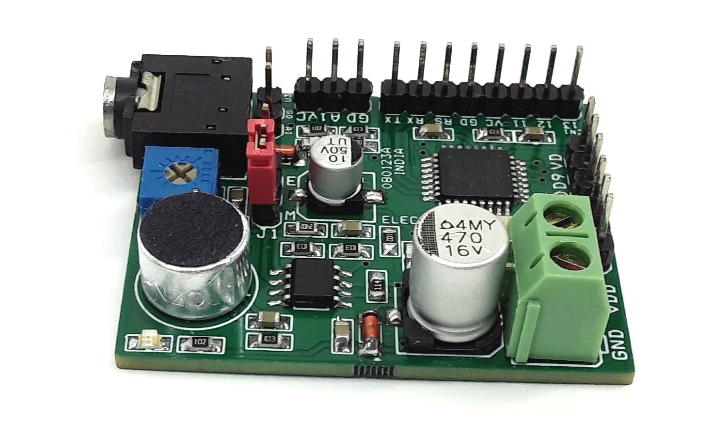
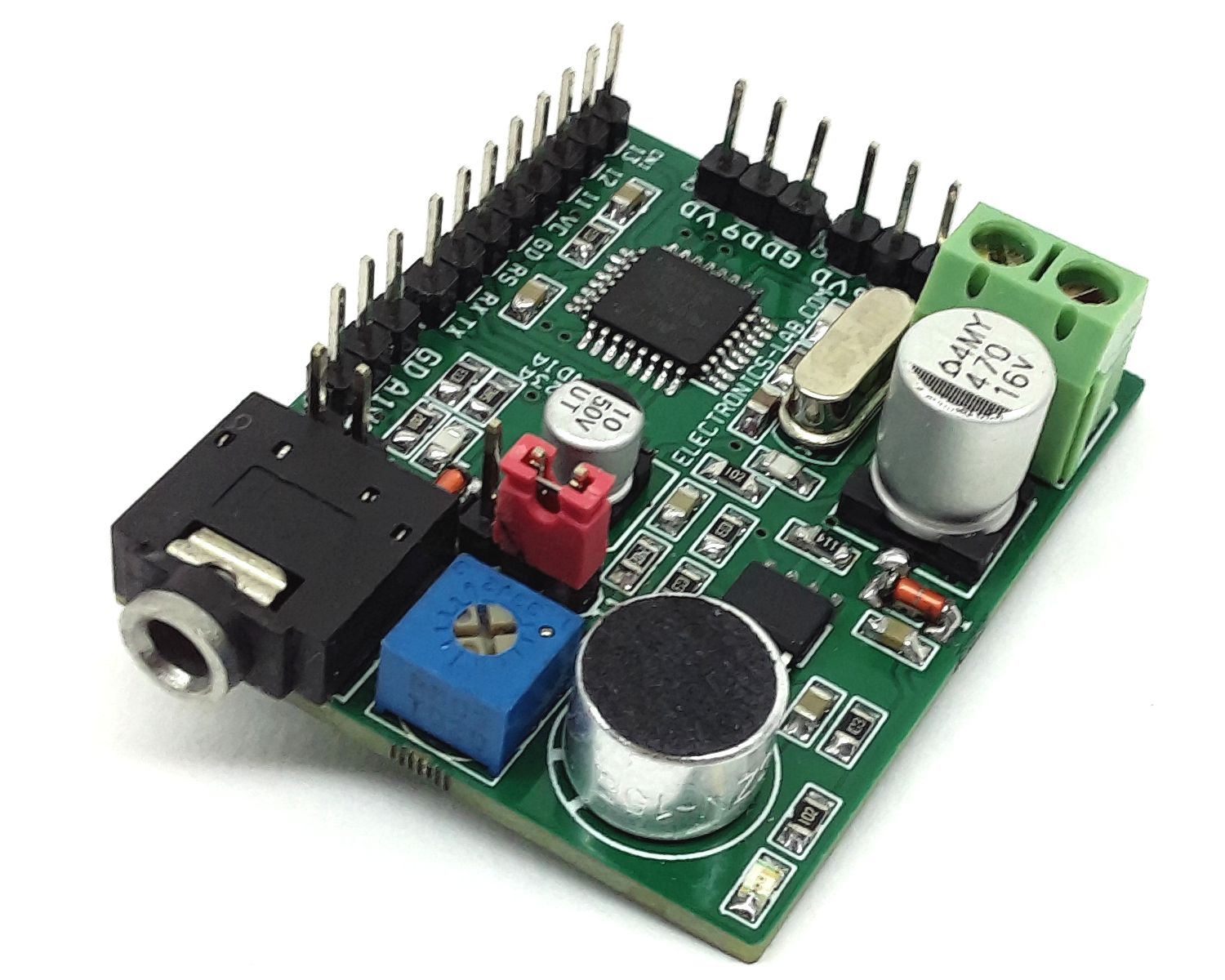
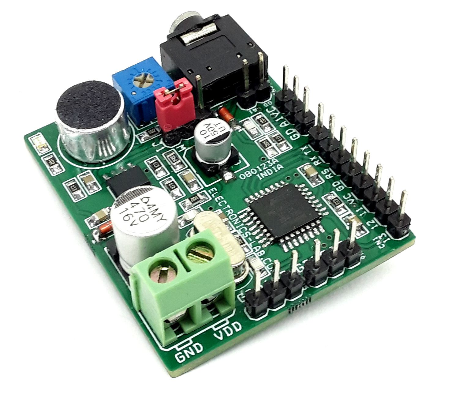
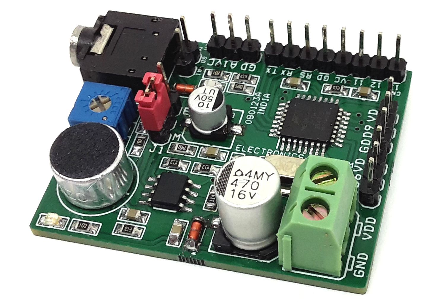
The project presented here is made for applications such as Animatronics, Puppeteer, sound-responsive toys, and robotics. The board is Arduino compatible and consists of LM358 OPAMP, ATMEGA328 microcontroller, microphone, and a few other components. The project moves the RC servo once receives any kind of sound. The rotation angle depends on the sound level, the higher the sound level the biggest the movement, in other words, the movement of the servo is proportional to the sound level. The microphone picks up the soundwave and converts it to an electrical signal, this signal is amplified by LM358 op-amp-based dual-stage amplifier, D1 helps to rectify the sinewave into DC, and C8 works as a filter capacitor that smooths the DC voltage. ATmega328 microcontroller converts this DC voltage into a suitable RC PWM signal.
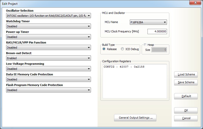
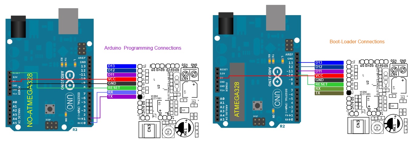
The project is Arduino compatible and an onboard connector is provided for the boot-loader and Arduino IDE programming. Arduino code is available as a download, and Atmega328 chips need to be programmed with a bootloader before uploading the code. Users may modify the code as per requirement. More information on burning the bootloader is here: https://www.arduino.cc/en/Tutorial/BuiltInExamples/ArduinoToBreadboard
Features
- Supply 5V to 6V DC (Battery Power Advisable)
- RC Servo Movement 180 Degrees with Loud sound
- Direct Sound Input Facility Using 3.5MM RC Jack
- On Board Jumper Selection for Micro-Phone Audio or External Audio Signal
- On Board Trimmer Potentiometer to Adjust the Signal Sensitivity
- Flexible Operation, Parameters Can be Changed using Arduino Code
- PCB Dimensions 44.45 x 36.20 mm
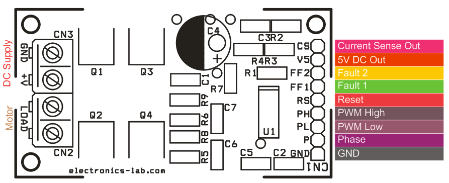
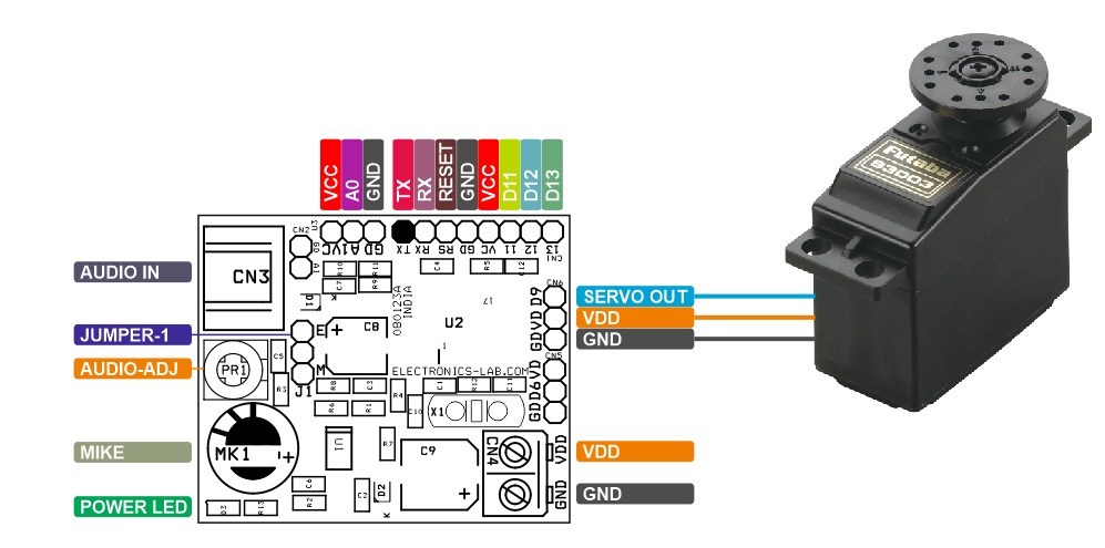
Connections and Other Details
- CN1 Arduino Programming and Boot-Load Connector: Pin 1 = TX, Pin 2 = RX, Pin 3 = Reset, Pin 4 = GND, Pin 5 = VCC 5V DC, Pin 6 = D11, Pin 7 = D12, Pin 8 = D13
- CN2 Direct Audio Input: Optional, Pin 1 Audio from External Speaker, Pin 2 = GND
- CN3 Stereo EP 3.5MM Female Connector for External Audio Signal Input from Speaker
- CN4 DC Input: Pin 1 VDD 5V to 6V DC, Pin 2 GND
- CN5: No USE – Optional
- CN6: RC Servo
- Jumper J1: Input Signal Source Selection (External Audio Signal or Microphone)
- PR1 Trimmer Potentiometer: Audio Signal Level Adjust
- MK1: Condenser Microphone
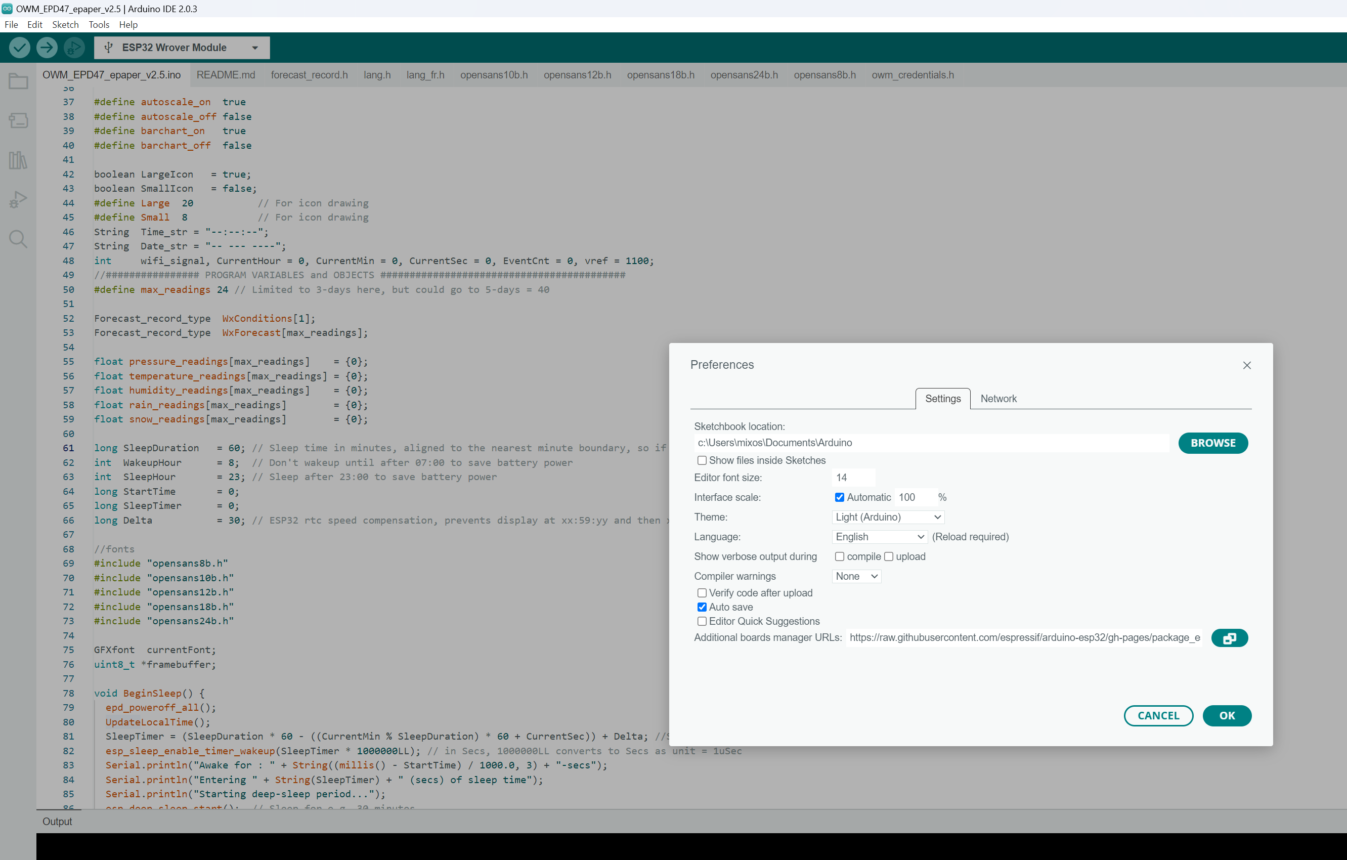
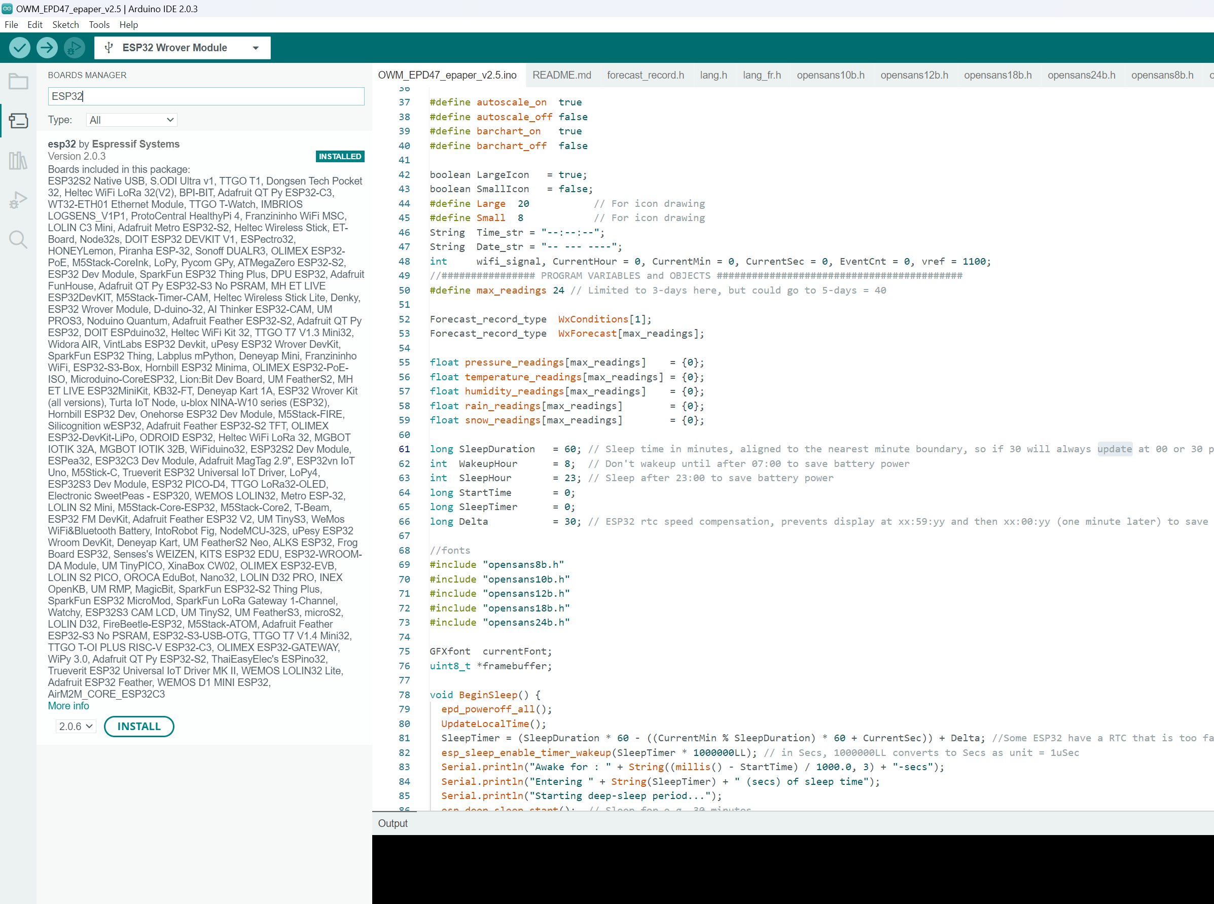
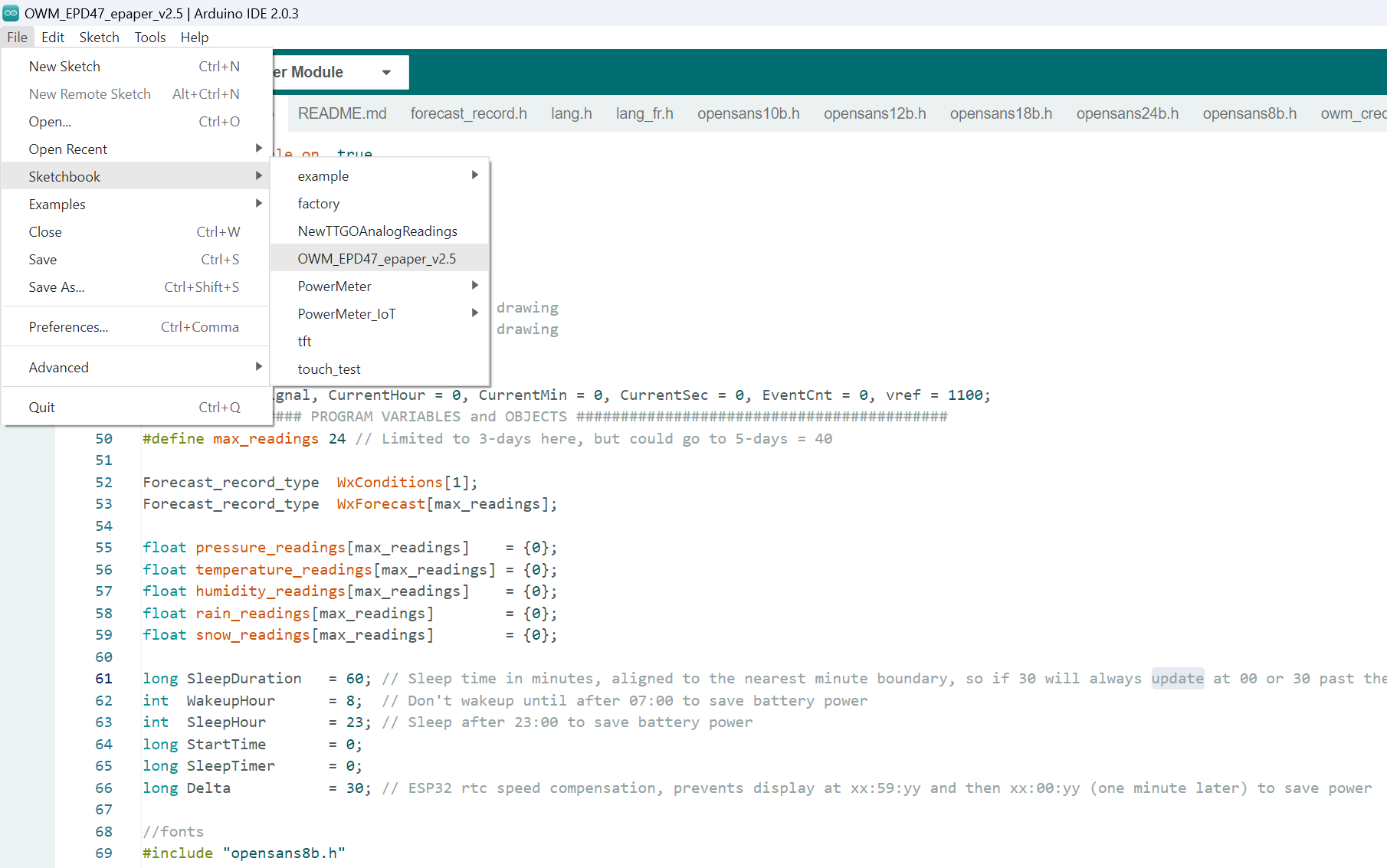
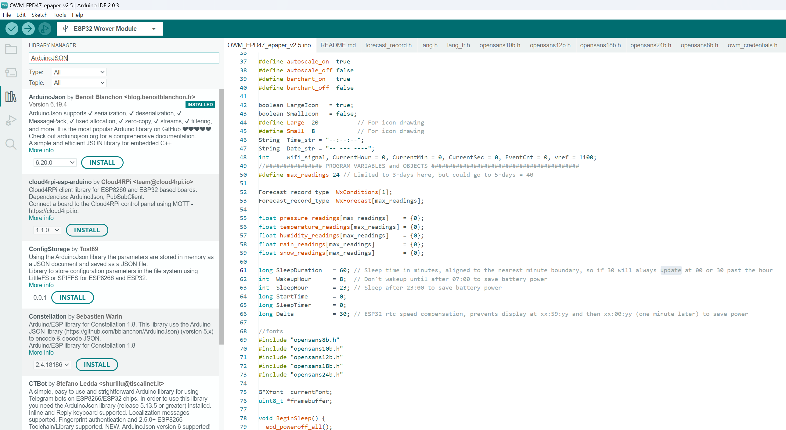
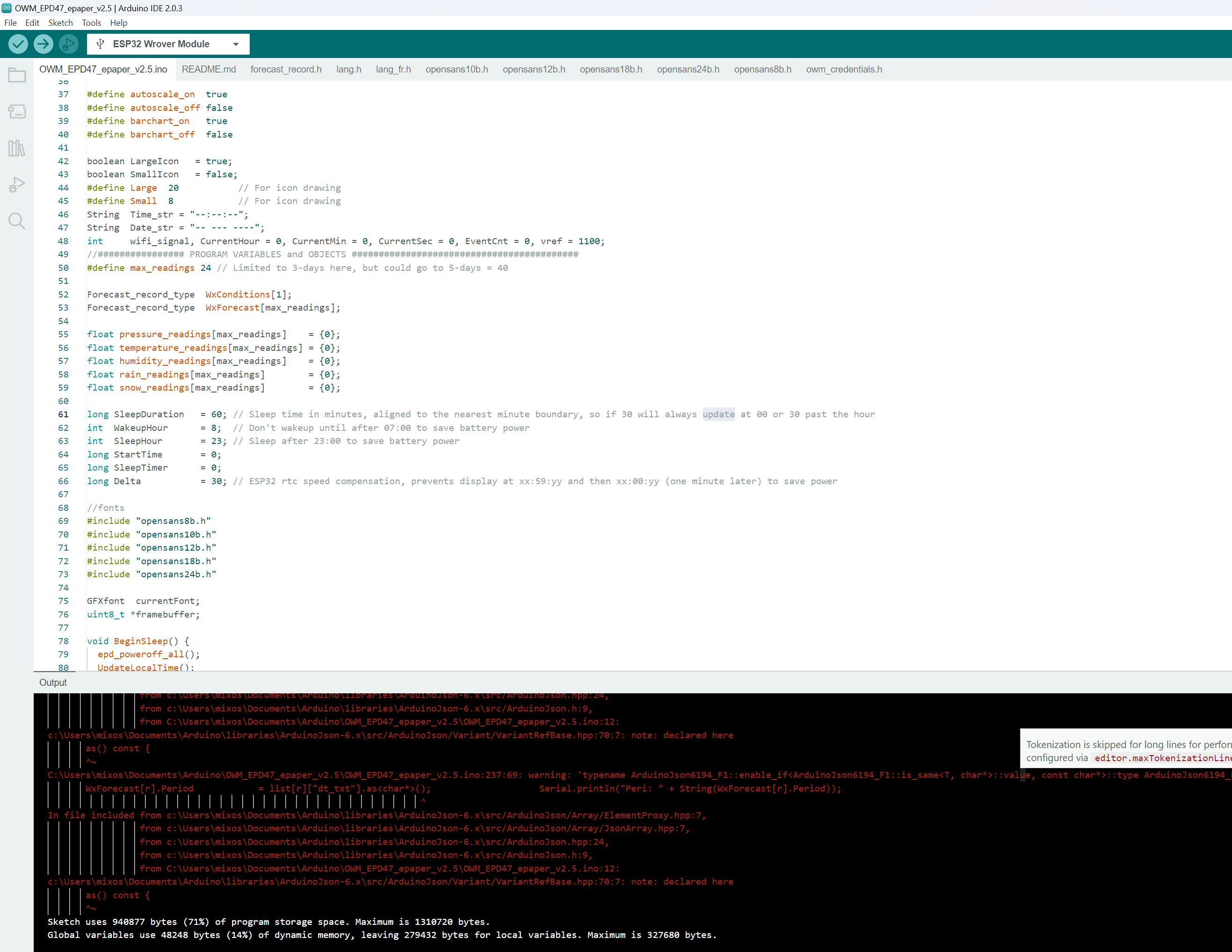
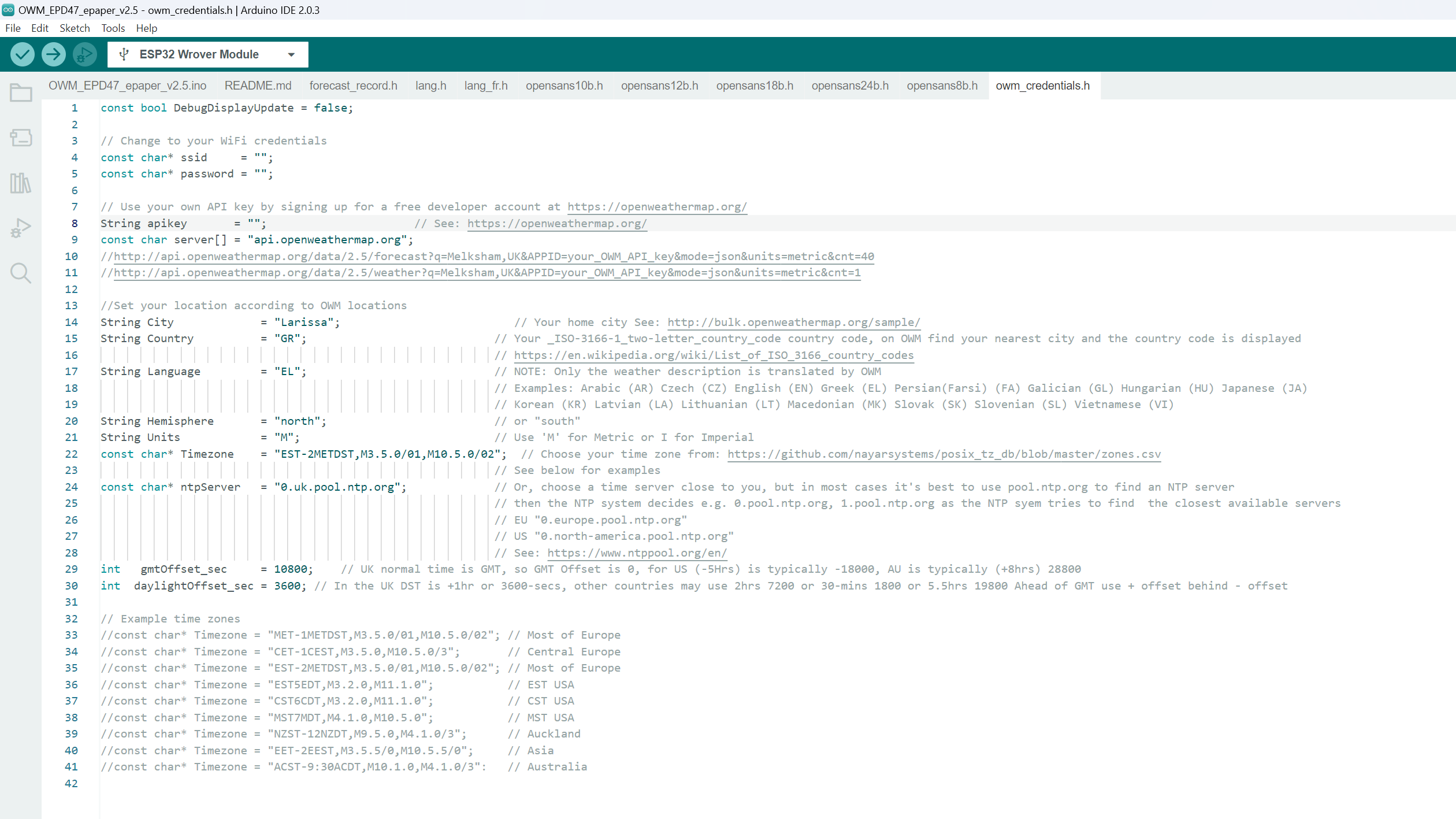
Arduino Programming
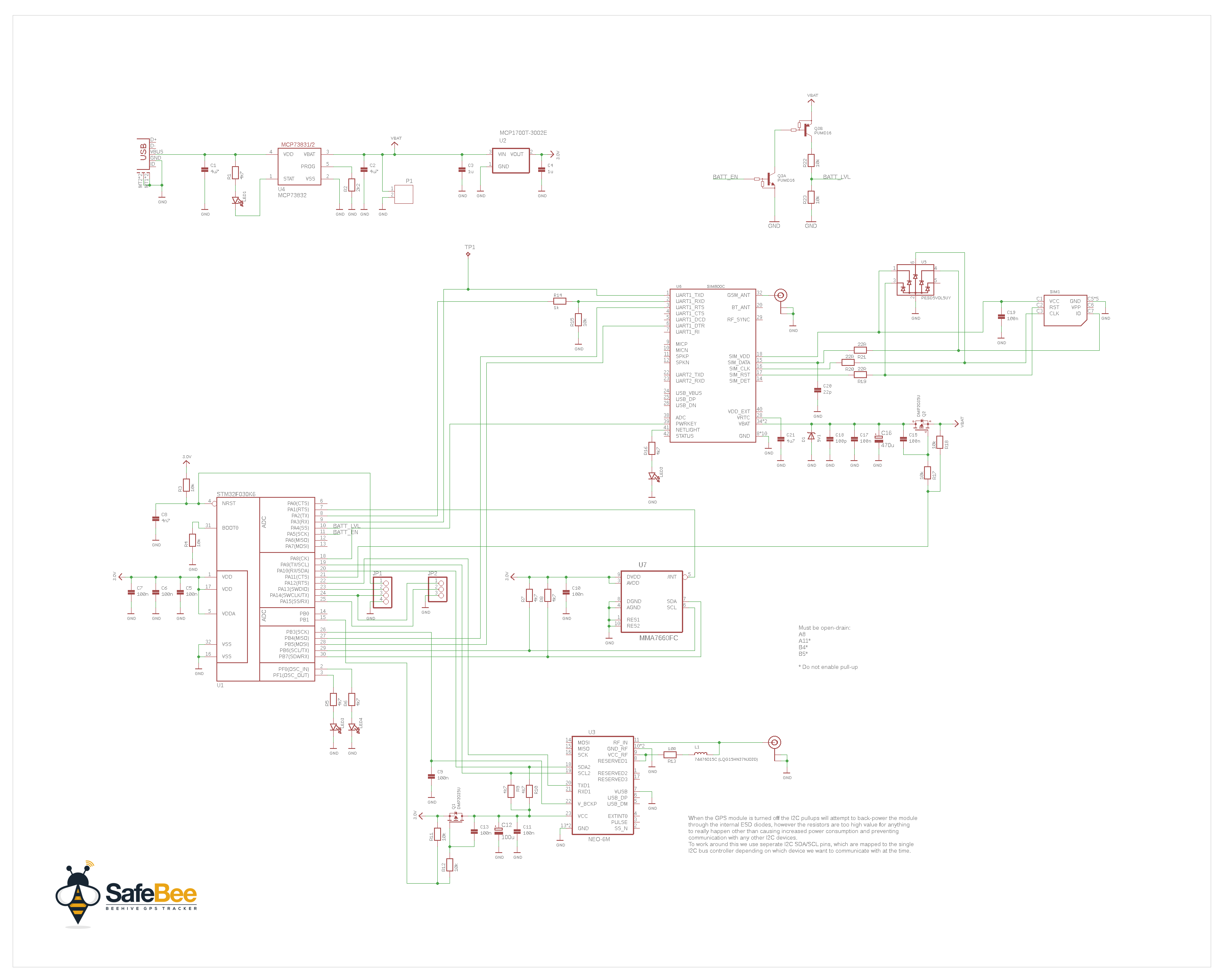
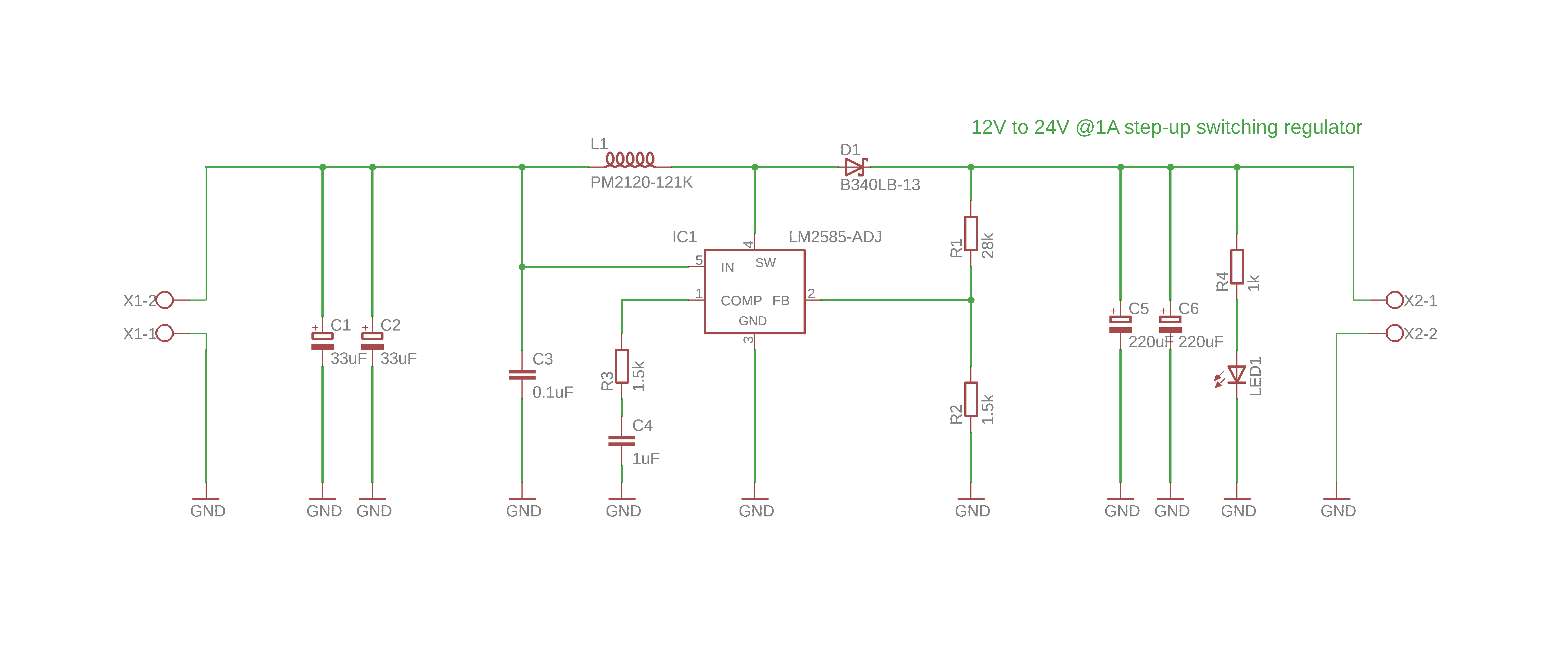
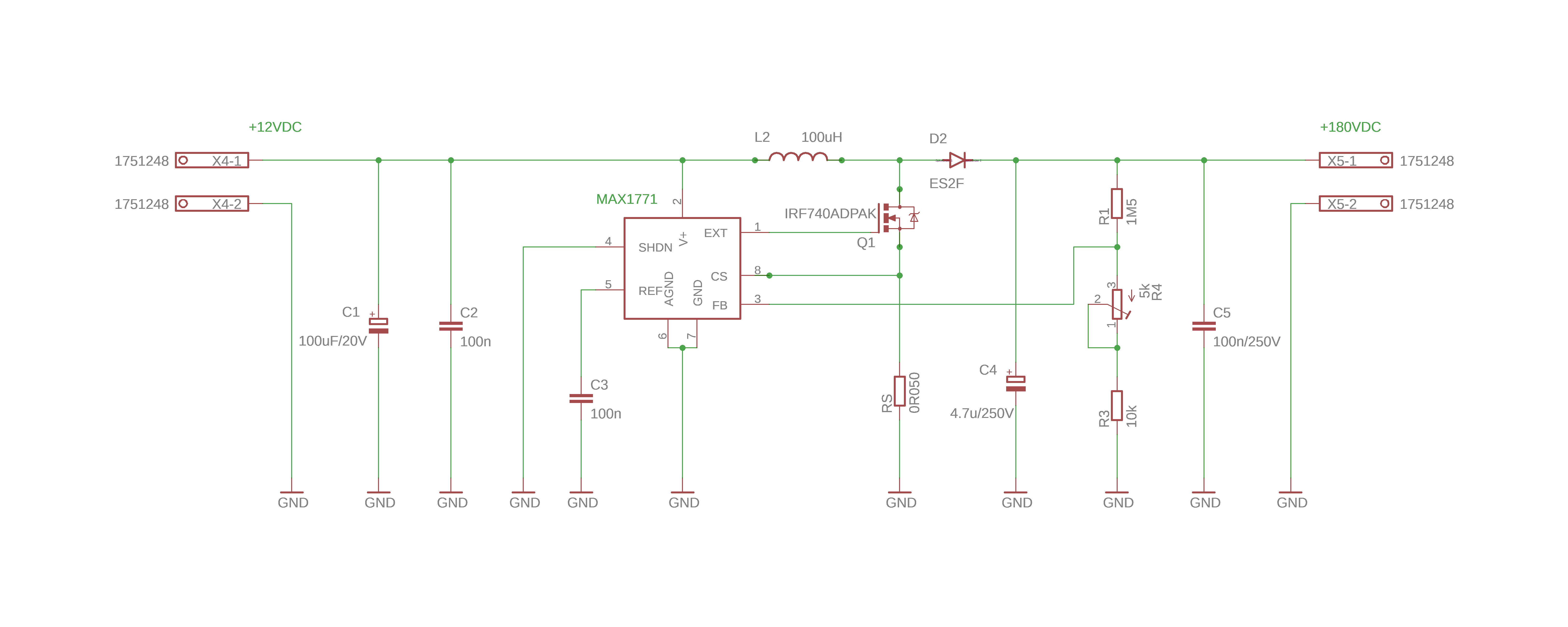
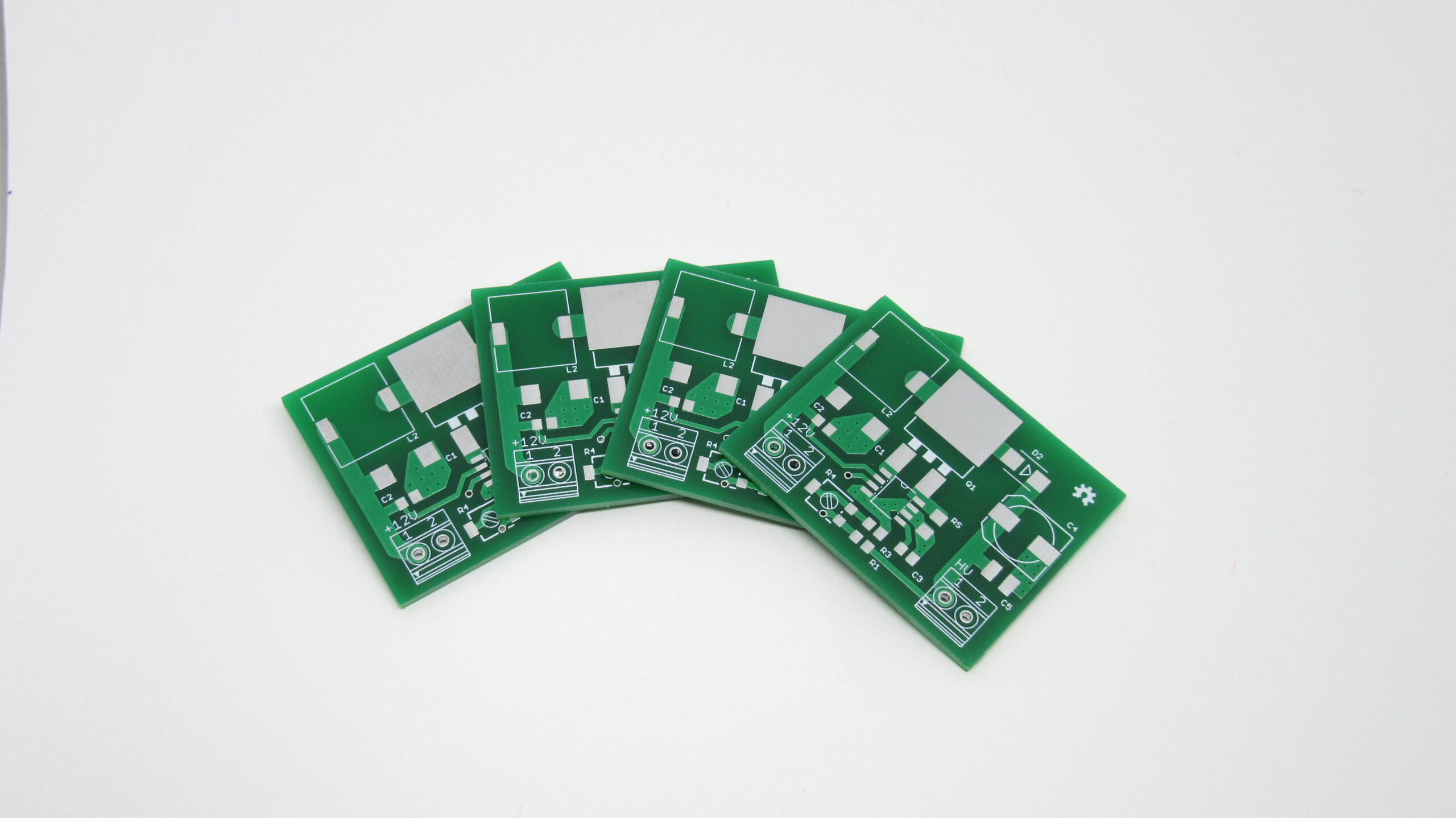
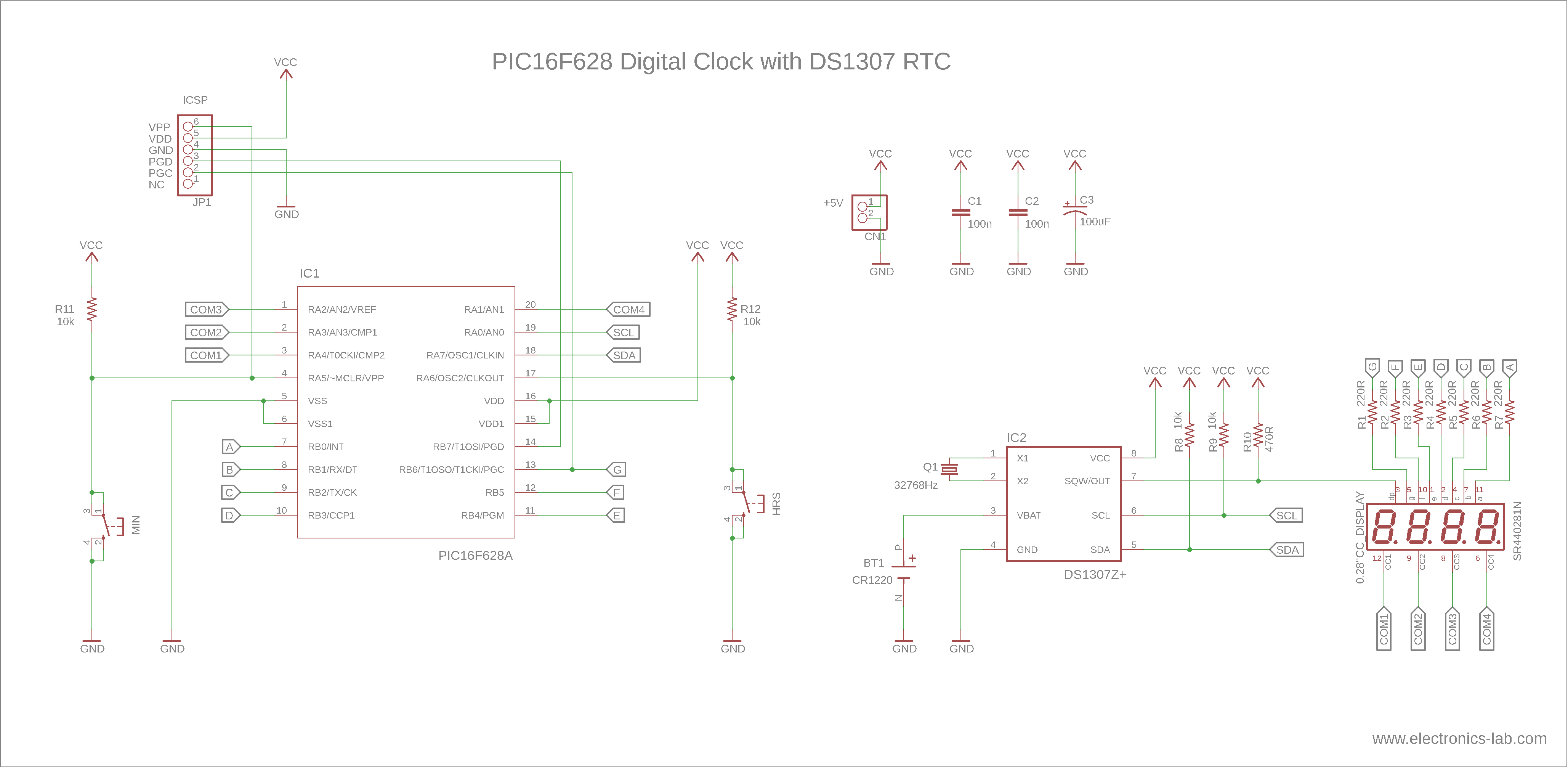
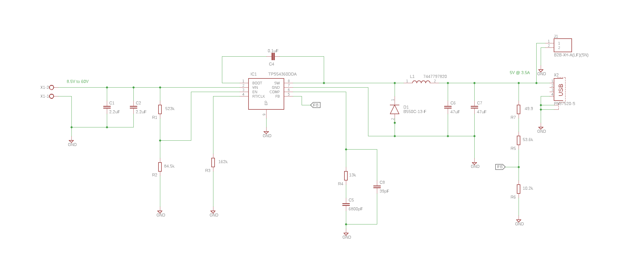
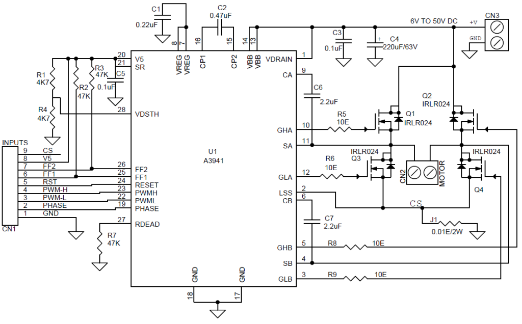
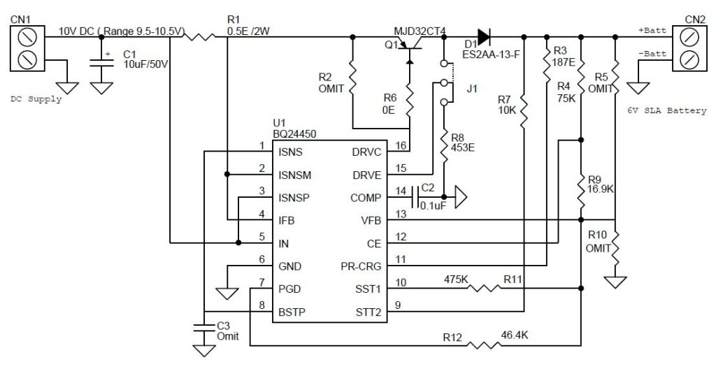
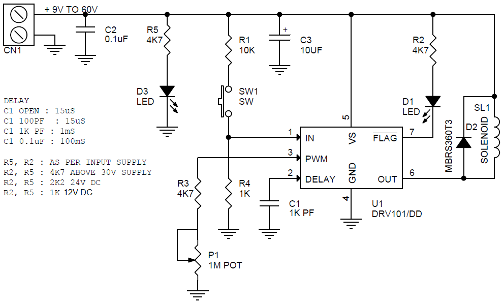
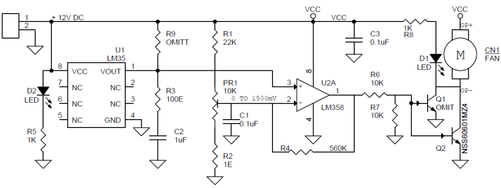
Schematic
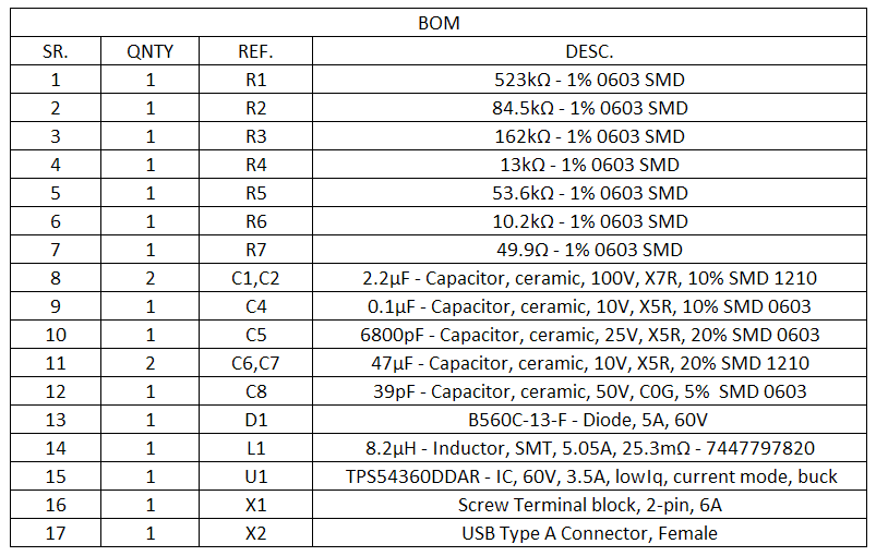
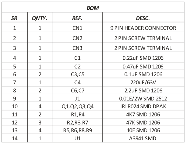
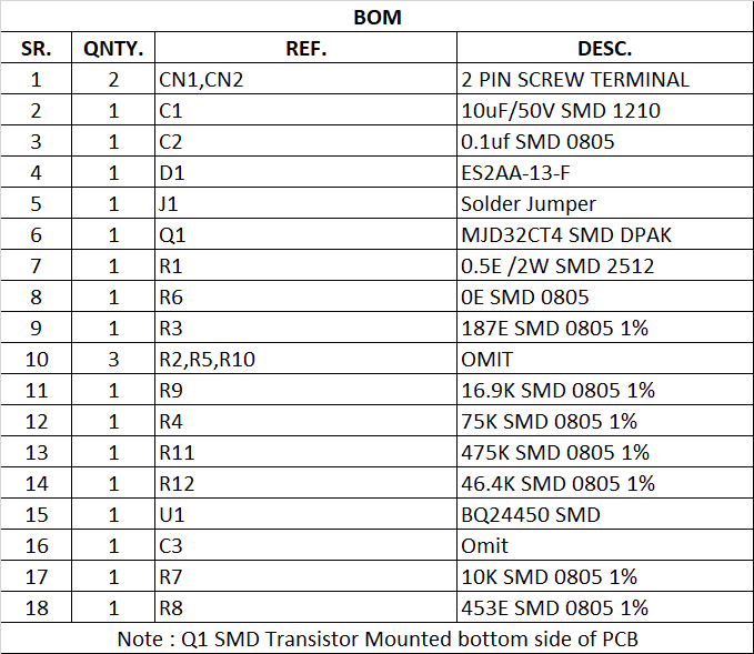
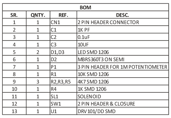
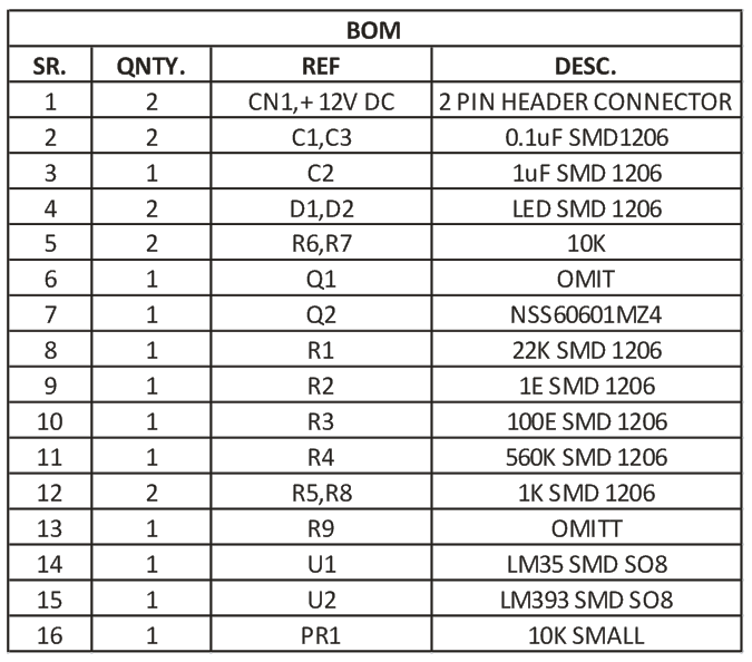
Parts List
| NO | QNTY. | REF. | DESC. | MANUFACTURER | SUPPLIER | SUPPLIER PART NO |
|---|---|---|---|---|---|---|
| 1 | 1 | CN1 | 8 PIN MALE HEADER PITCH 2.54MM | WURTH | DIGIKEY | 732-5321-ND |
| 2 | 1 | CN2 | 2 PIN MALE HEADER PITCH 2.54MM | WURTH | DIGIKEY | 732-5315-ND |
| 3 | 1 | CN3 | STEREO SOCKET 3.5MM FEMALE | CUI DEVICES | DIGIKEY | CP1-3525N-ND |
| 4 | 1 | CN4 | 2 PIN SCREW TERMINAL PITCH 5.08MM | PHOENIX | DIGIKEY | 277-1247-ND |
| 5 | 1 | CN5 | 3 PIN MALE HEADER PITCH 2.54MM | WURTH | DIGIKEY | 732-5316-ND |
| 6 | 1 | CN6 | 3 PIN MALE HEADER PITCH 2.54MM | WURTH | DIGIKEY | 732-5316-ND |
| 7 | 1 | C1 | 10uF/10V CERAMIC SMD SIZE 0805 | MURATA/YAGEO | DIGIKEY | |
| 8 | 6 | C2,C3,C5,C12,C4,C6 | 100nF/50V CERAMIC SMD SIZE 0805 | MURATA/YAGEO | DIGIKEY | |
| 9 | 1 | SHUNT | SHUNT FOR JUMPER | SULLINS CONNCT | DIGIKEY | S9001-ND |
| 10 | 3 | U3,C7,R10 | DNP | |||
| 11 | 1 | C8 | 10uF/50V SMD ELECTROLYTIC | WURTH | DIGIKEY | 732-8451-1-ND |
| 12 | 1 | C9 | 470uF/16V SMD ELECTROLYTIC | ELITE | DIGIKEY | 4191-CEE1C471MCB08A5CT-ND |
| 13 | 2 | C10,C11 | 22PF/50V SMD SIZE 0805 | MURATA/YAGEO | DIGIKEY | |
| 14 | 2 | D1,D2 | 1N4148 SMD | ONSEMI | DIGIKEY | FDLL4148CT-ND |
| 15 | 1 | D3 | LED RED SMD SIZE 0805 | LITE ON INC | DIGIKEY | 160-1427-1-ND |
| 16 | 1 | J1 | 3 PIN MALE HEADER PITCH 2.54MM | WURTH | DIGIKEY | 732-5316-ND |
| 17 | 1 | MK1 | CONDENSOR MICE | PUI AUDIO | DIGIKEY | 668-1484-ND |
| 18 | 6 | R1,R2,R5,R6,R7,R11 | 10K 5% SMD SIZE 0805 | MURATA/YAGEO | DIGIKEY | |
| 19 | 3 | R3,R4,R13 | 1K 5% SMD SIZE 0805 | MURATA/YAGEO | DIGIKEY | |
| 20 | 1 | R8 | 24K 5% SMD SIZE 0805 | MURATA/YAGEO | DIGIKEY | |
| 21 | 1 | R9 | 1E 5% SMD SIZE 0805 | MURATA/YAGEO | DIGIKEY | |
| 22 | 1 | R12 | 1M 5% SMD SIZE 0805 | MURATA/YAGEO | DIGIKEY | |
| 23 | 1 | U1 | LM358 SMD SOIC8 | TI | DIGIKEY | 296-18457-1-ND |
| 24 | 1 | U2 | ATMEGA328TQPF-32 | MICROCHIP | DIGIKEY | ATMEGA328PB-AURCT-ND |
| 25 | 1 | X1 | 16Mhz | ECS INC | DIGIKEY | X1103-ND |
| 26 | 1 | PR1 | 10K TRIMMER POT | KYOCERA | DIGIKEY | 478-601030-ND |
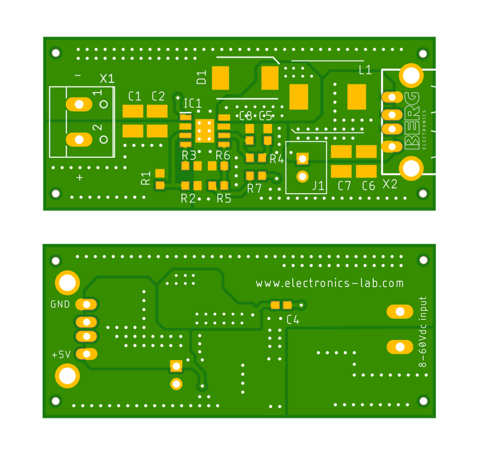
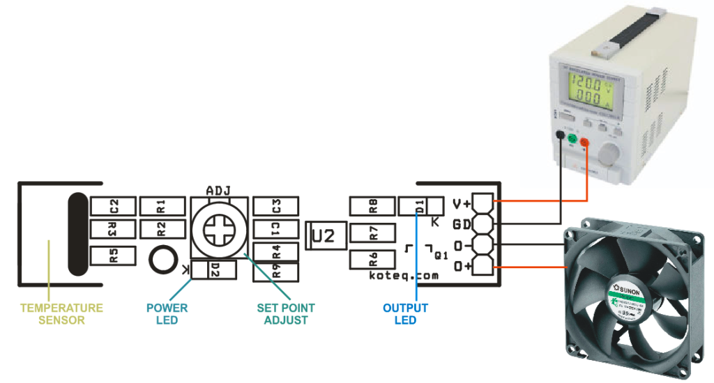
Connections
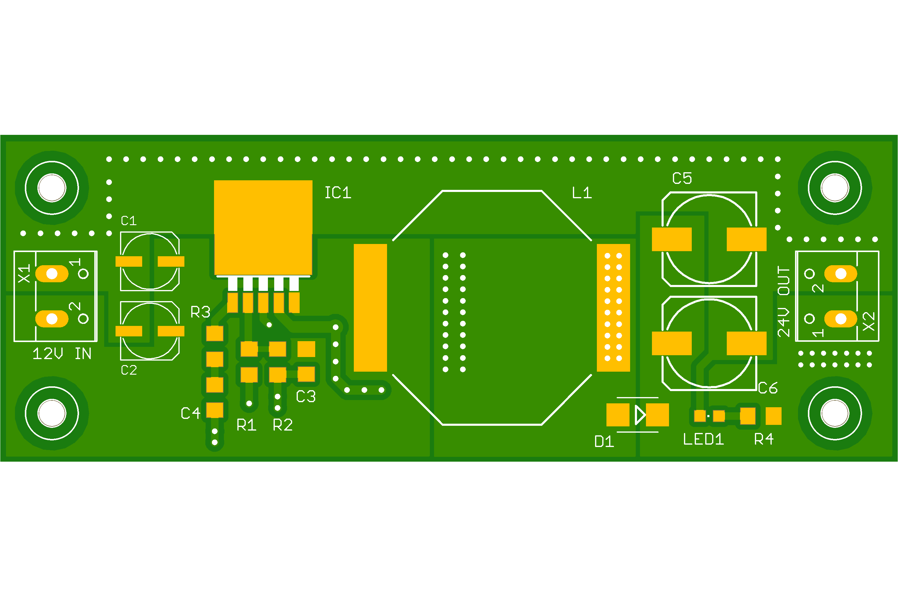
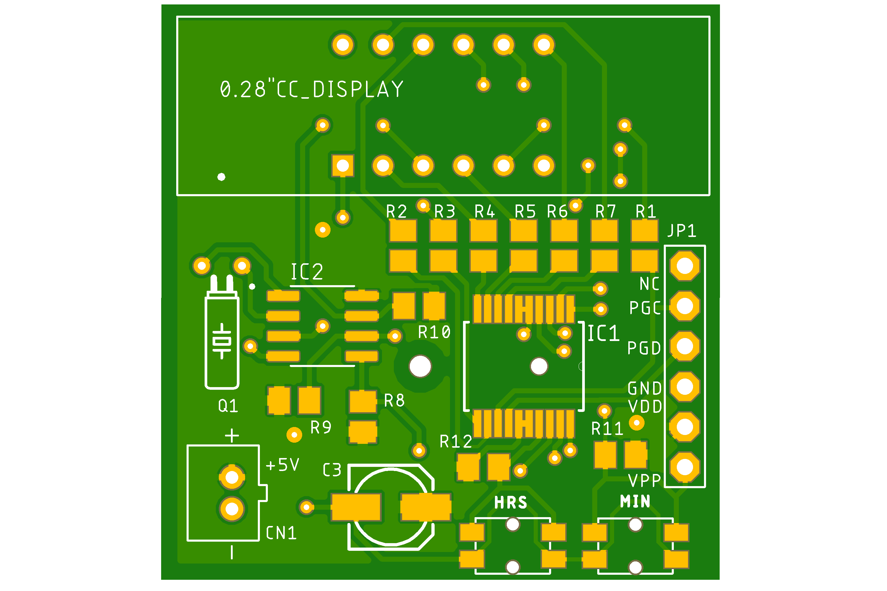
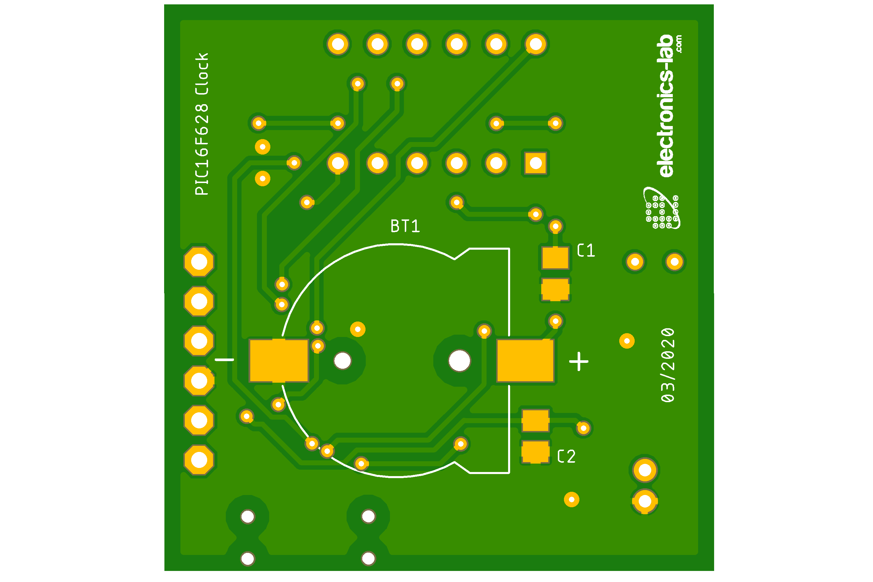
Gerber View
[PCBGerberVTool url=”https://www.electronics-lab.com/wp-content/uploads/2023/05/GERBER-3.zip”]Code
/*
 Controlling a servo position using a potentiometer (variable resistor)
 by Michal Rinott <http://people.interaction-ivrea.it/m.rinott>

 modified on 8 Nov 2013
 by Scott Fitzgerald
 http://www.arduino.cc/en/Tutorial/Knob
*/

#include <Servo.h>

Servo myservo;  // create servo object to control a servo

int potpin = A2;  // analog pin used to connect the potentiometer
int val;    // variable to read the value from the analog pin

void setup() {
  myservo.attach(6);  // attaches the servo on pin 6 to the servo object
}

void loop() {
  val = analogRead(potpin);            // reads the value of the potentiometer (value between 0 and 60)
  val = map(val, 0, 60, 0, 180);     // scale it for use with the servo (value between 0 and 180)
  myservo.write(val);                  // sets the servo position according to the scaled value
  delay(15);                           // waits for the servo to get there
}
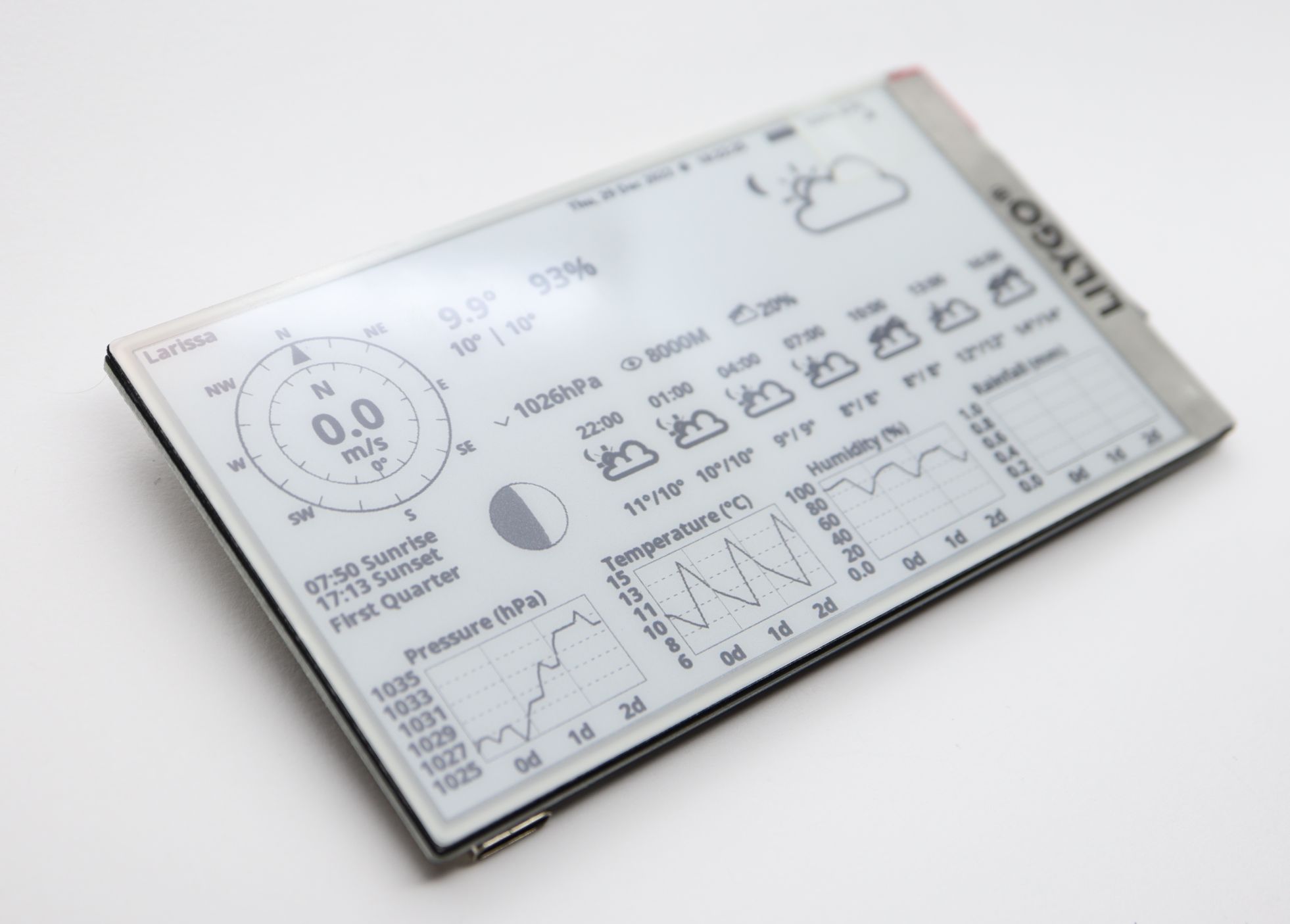
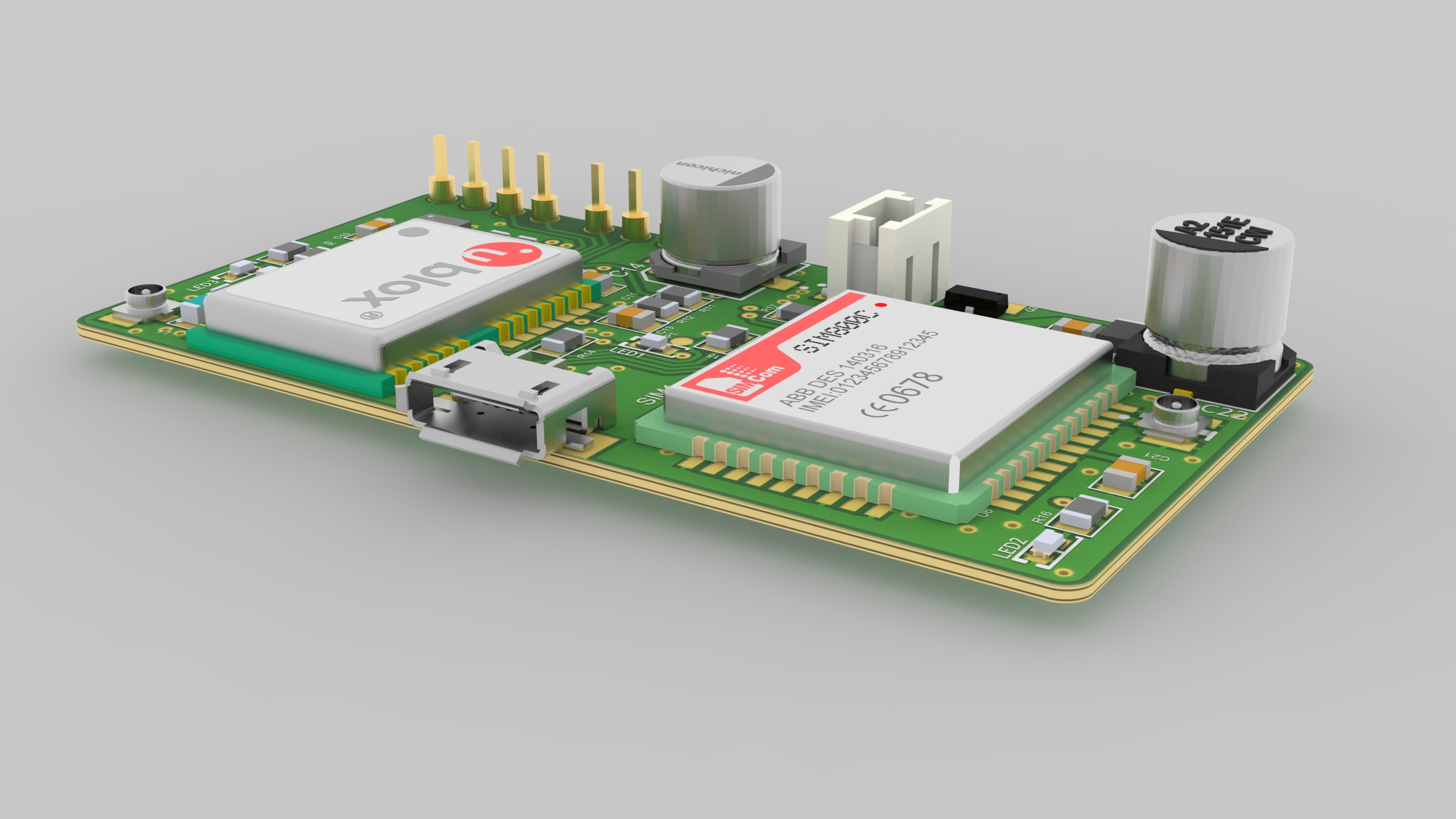
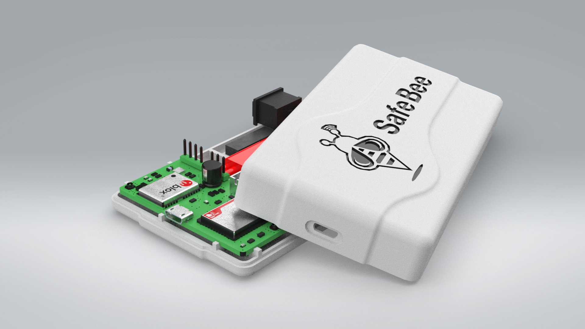
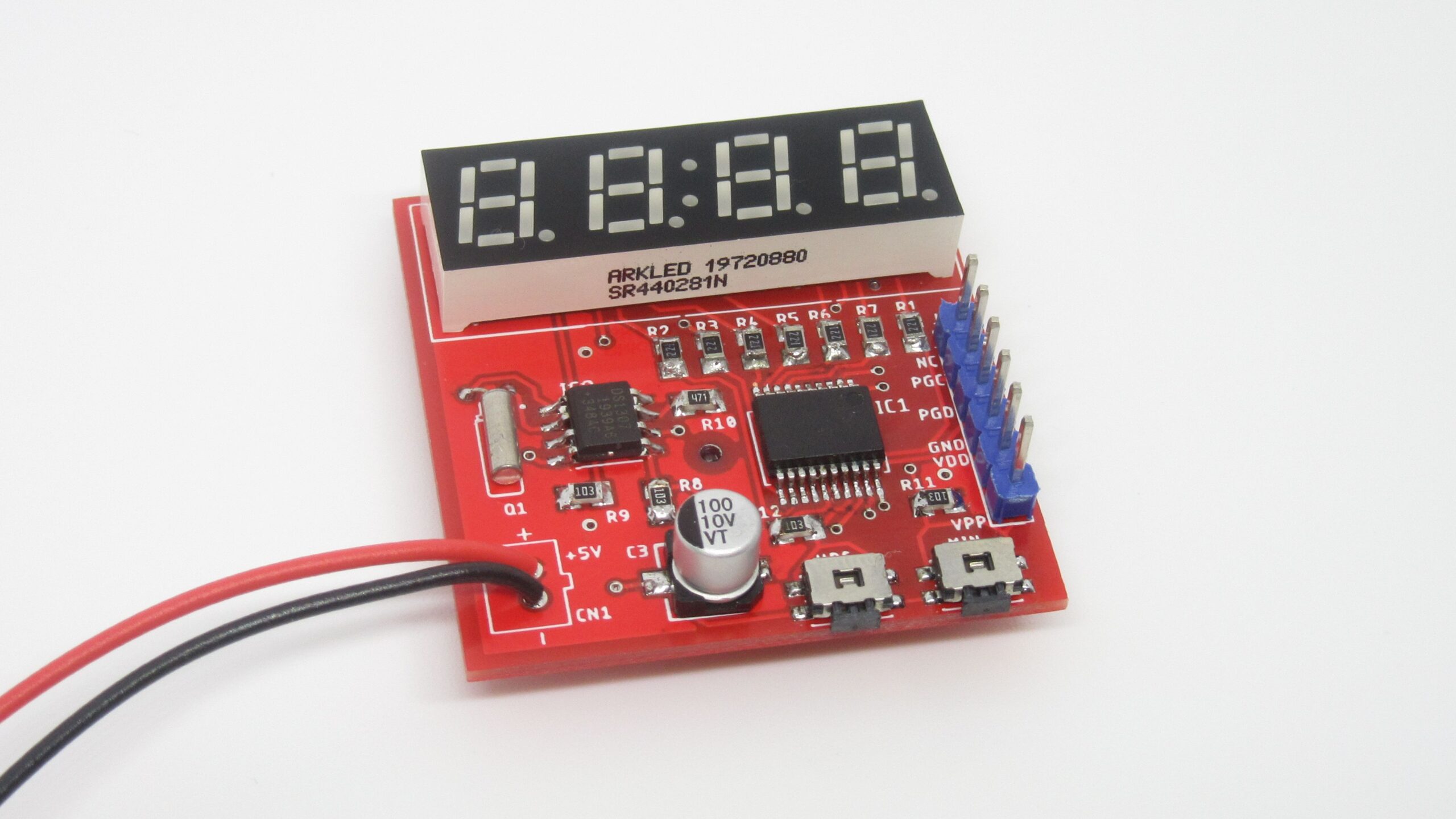
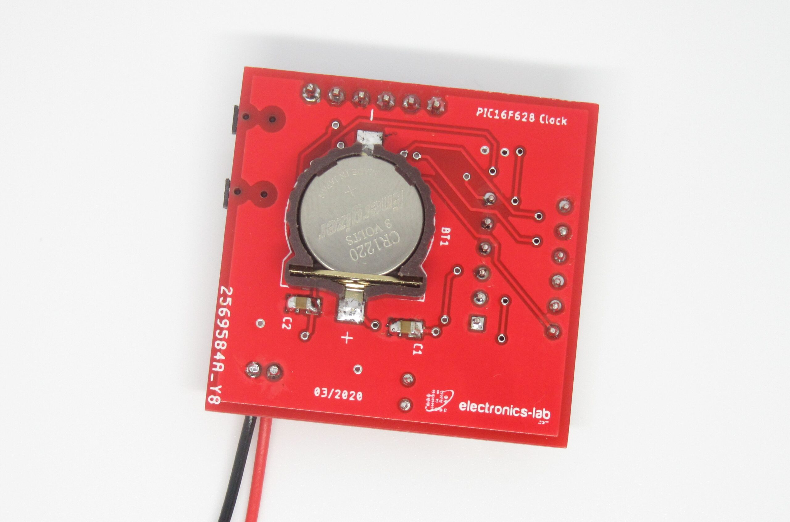
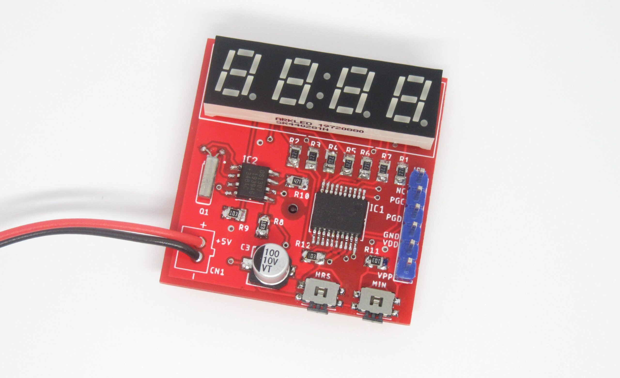
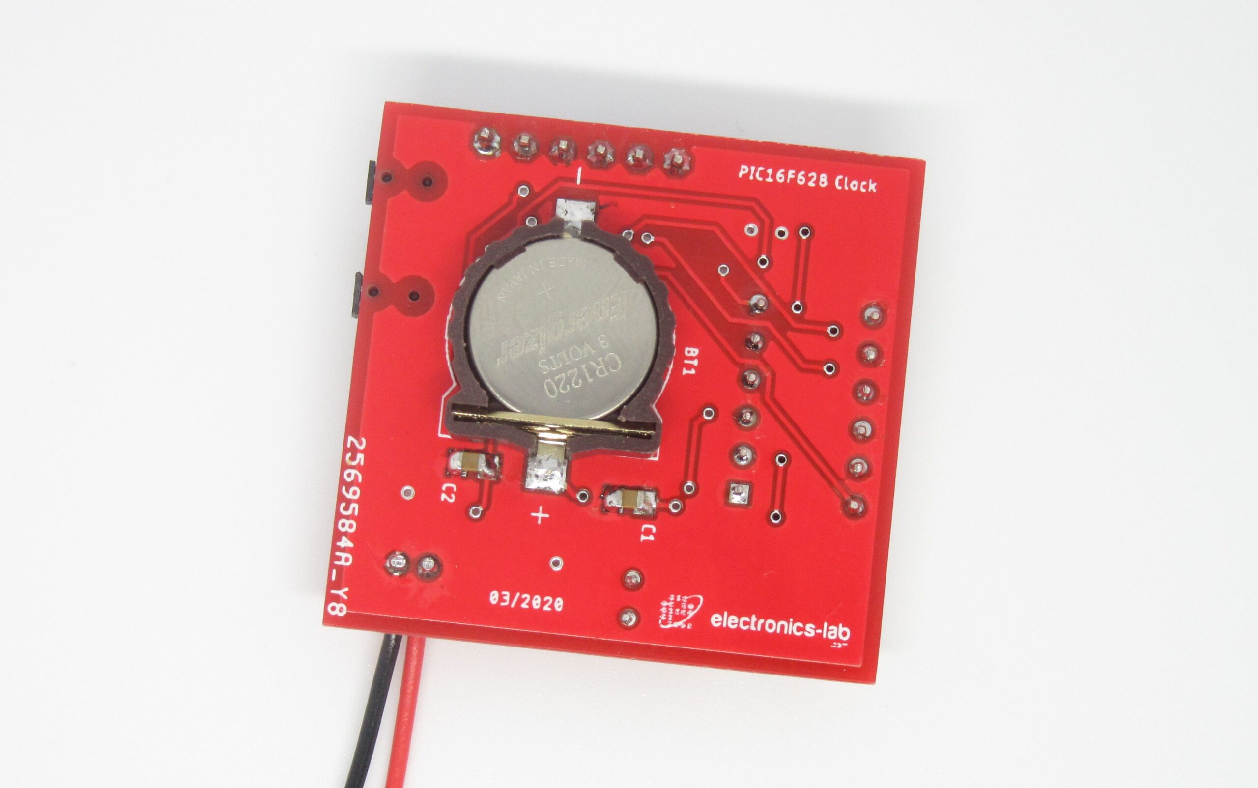
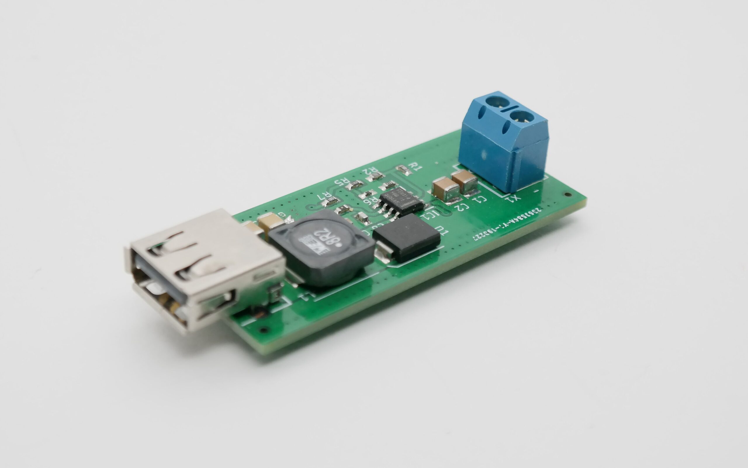
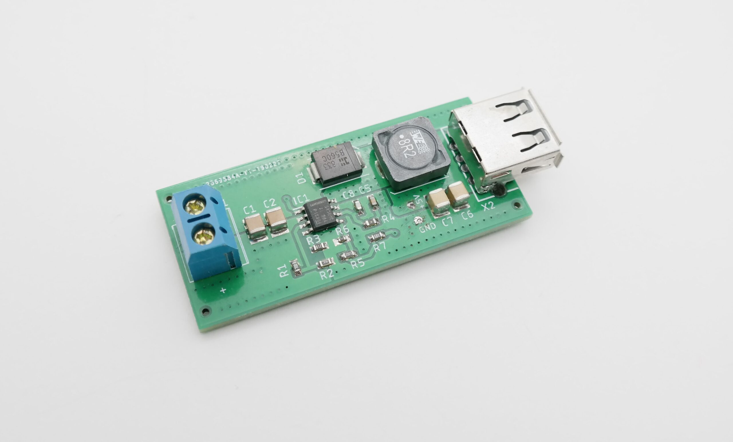
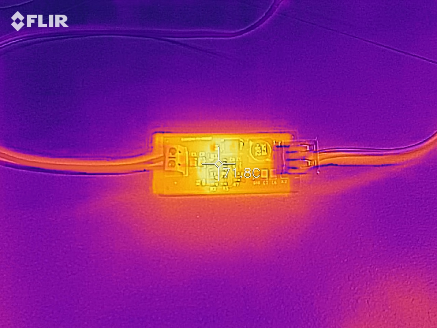
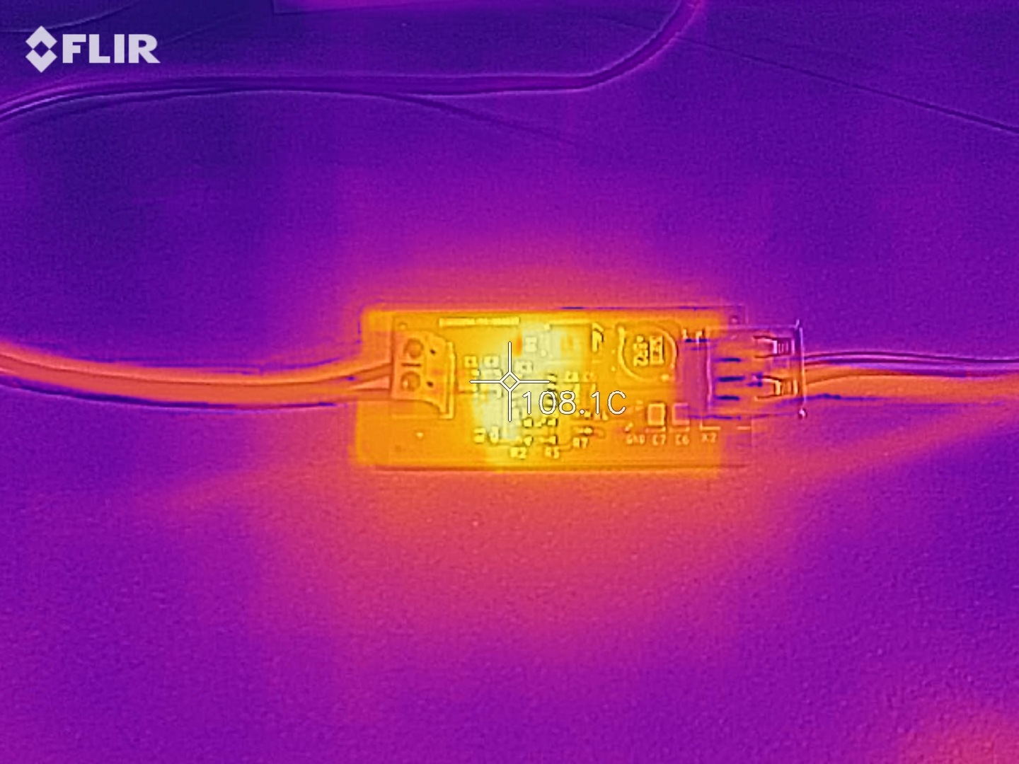
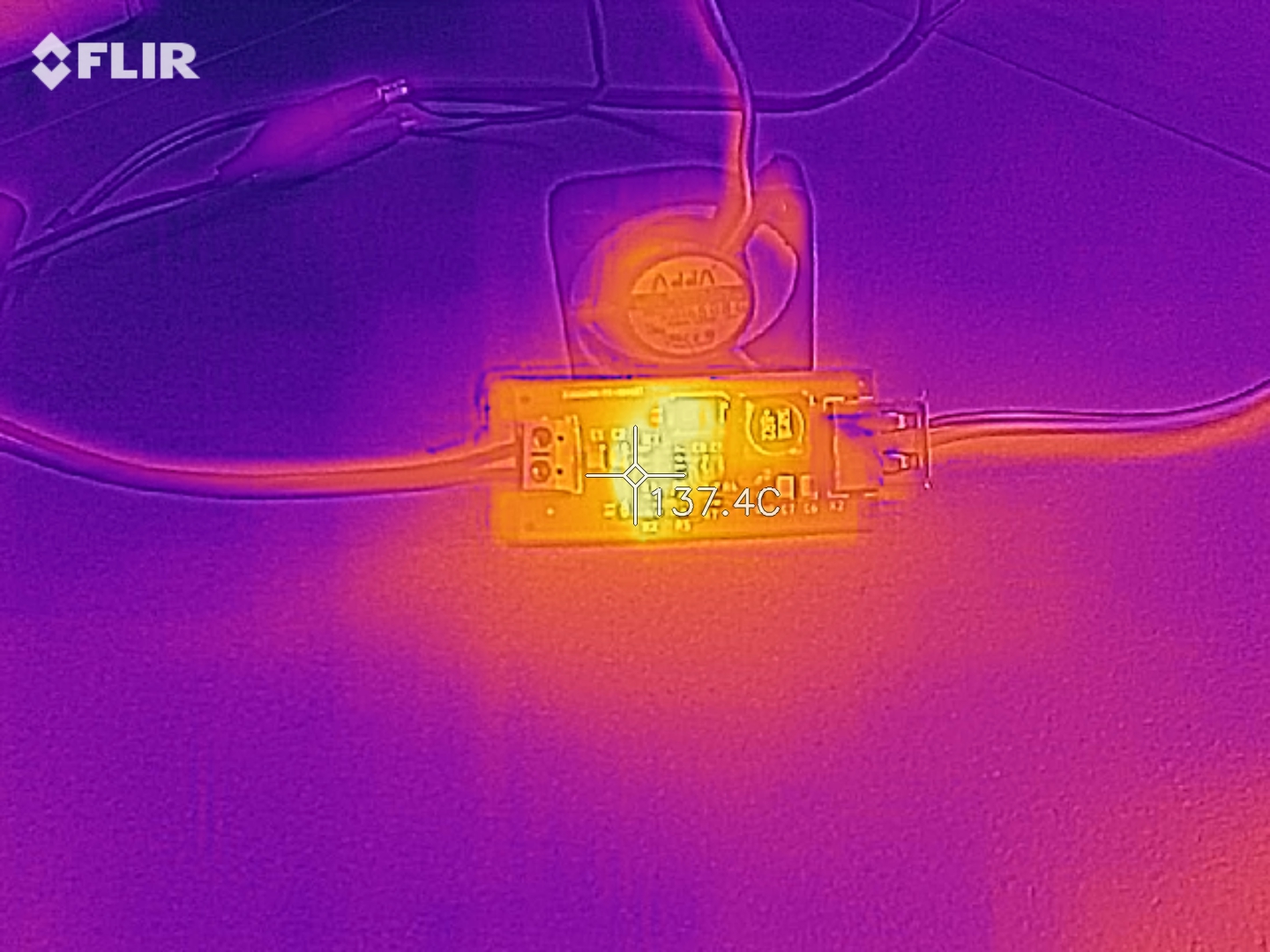
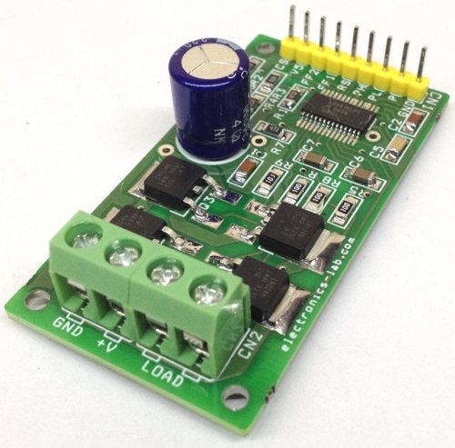
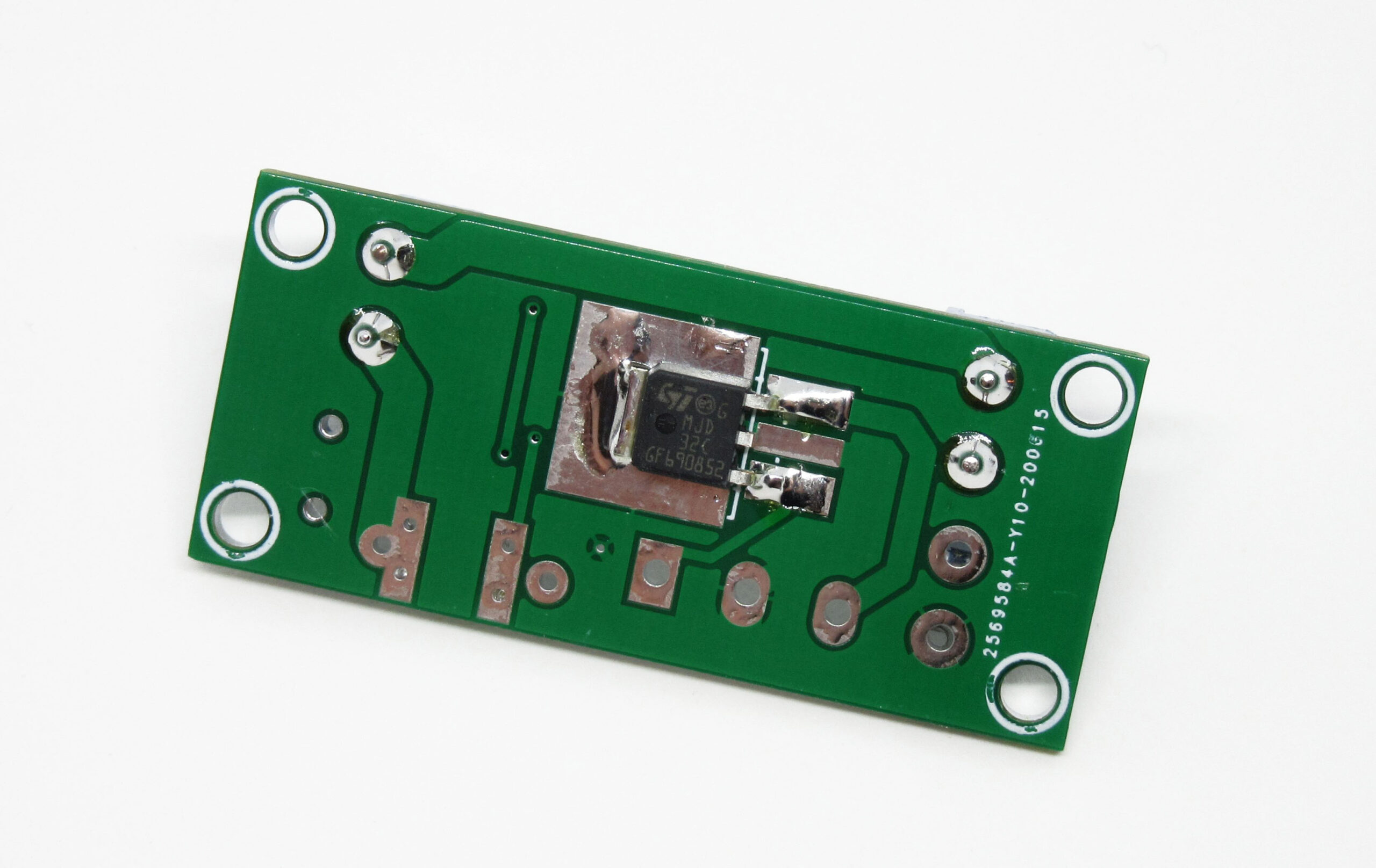
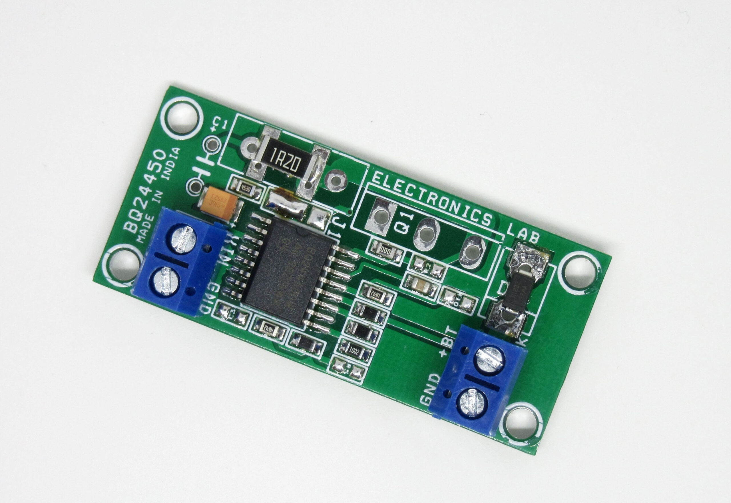
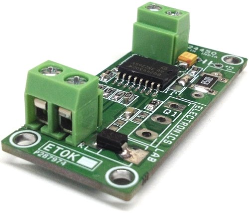
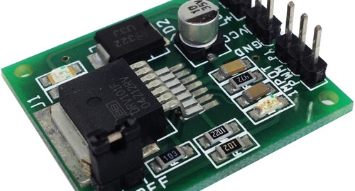
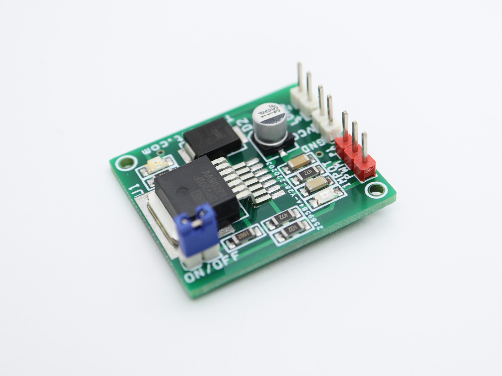
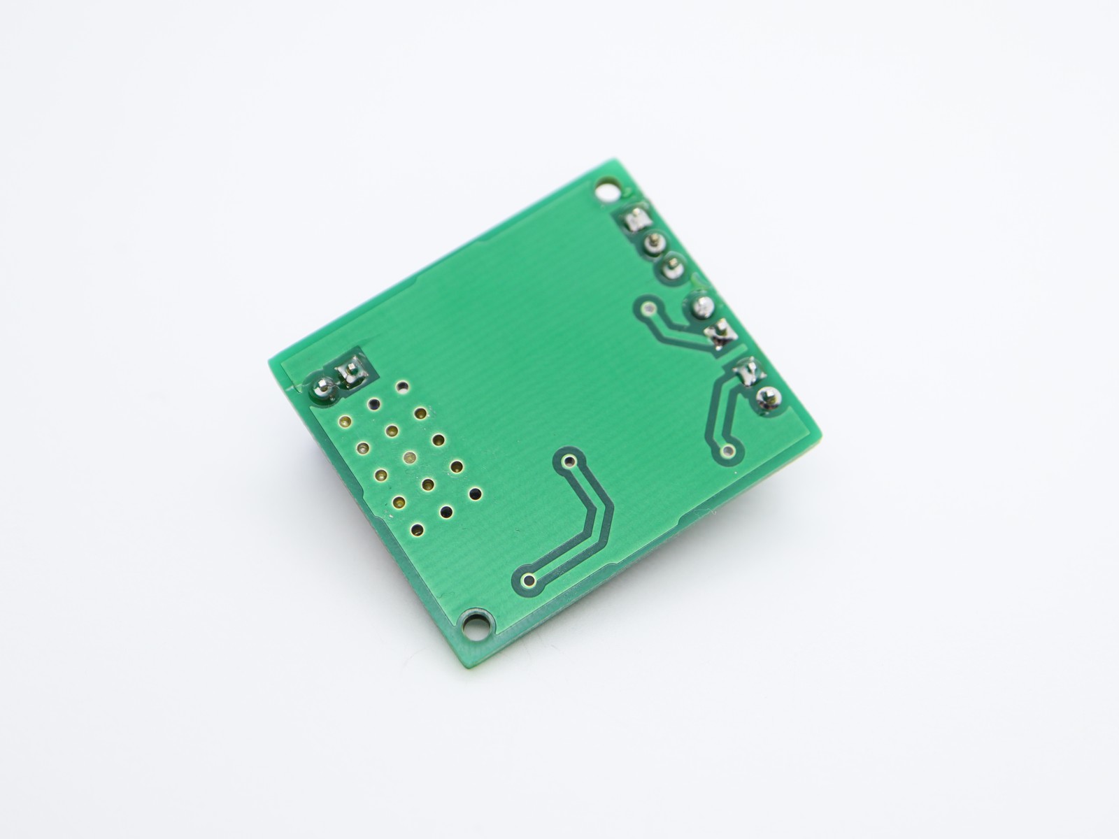
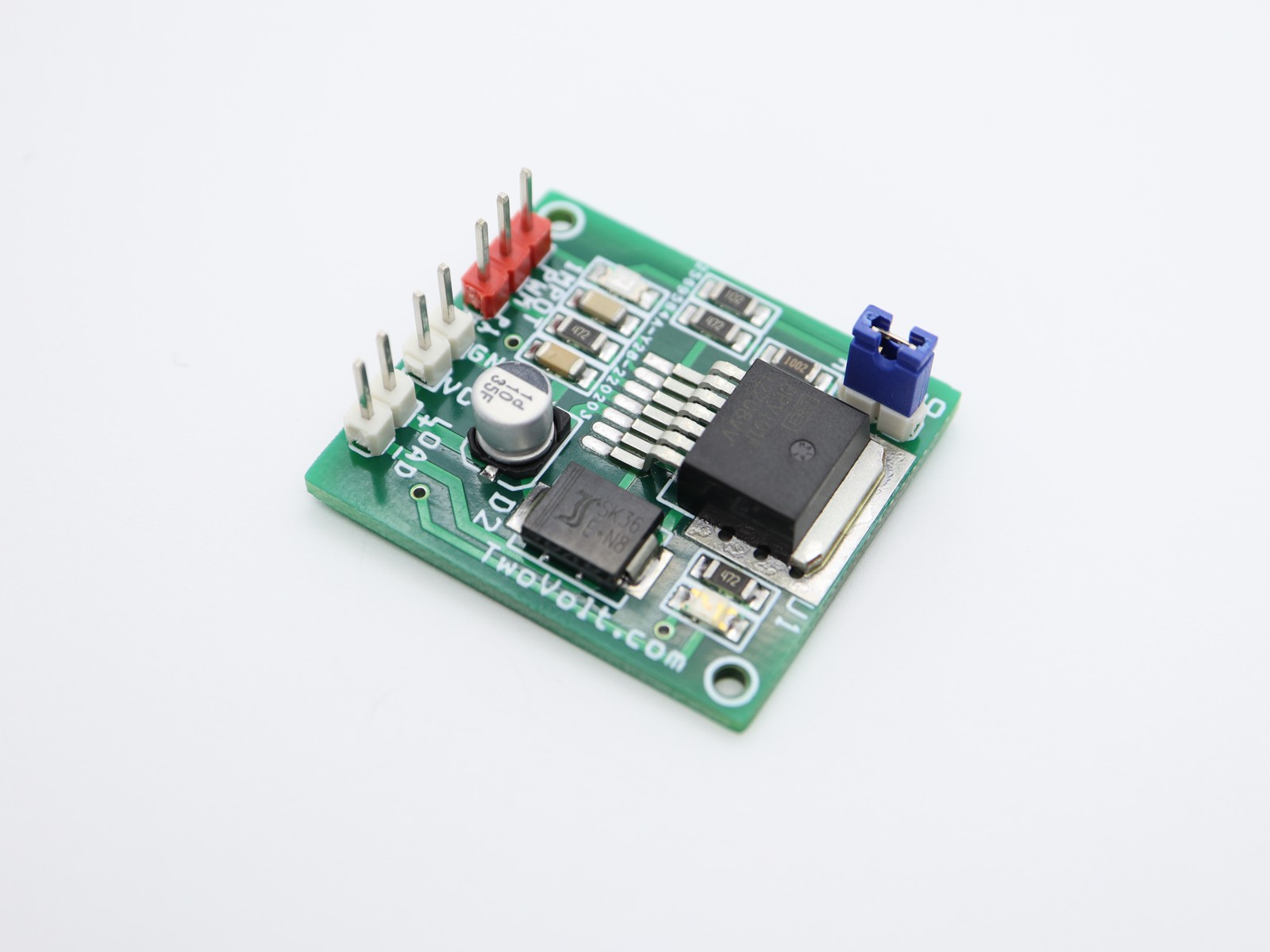
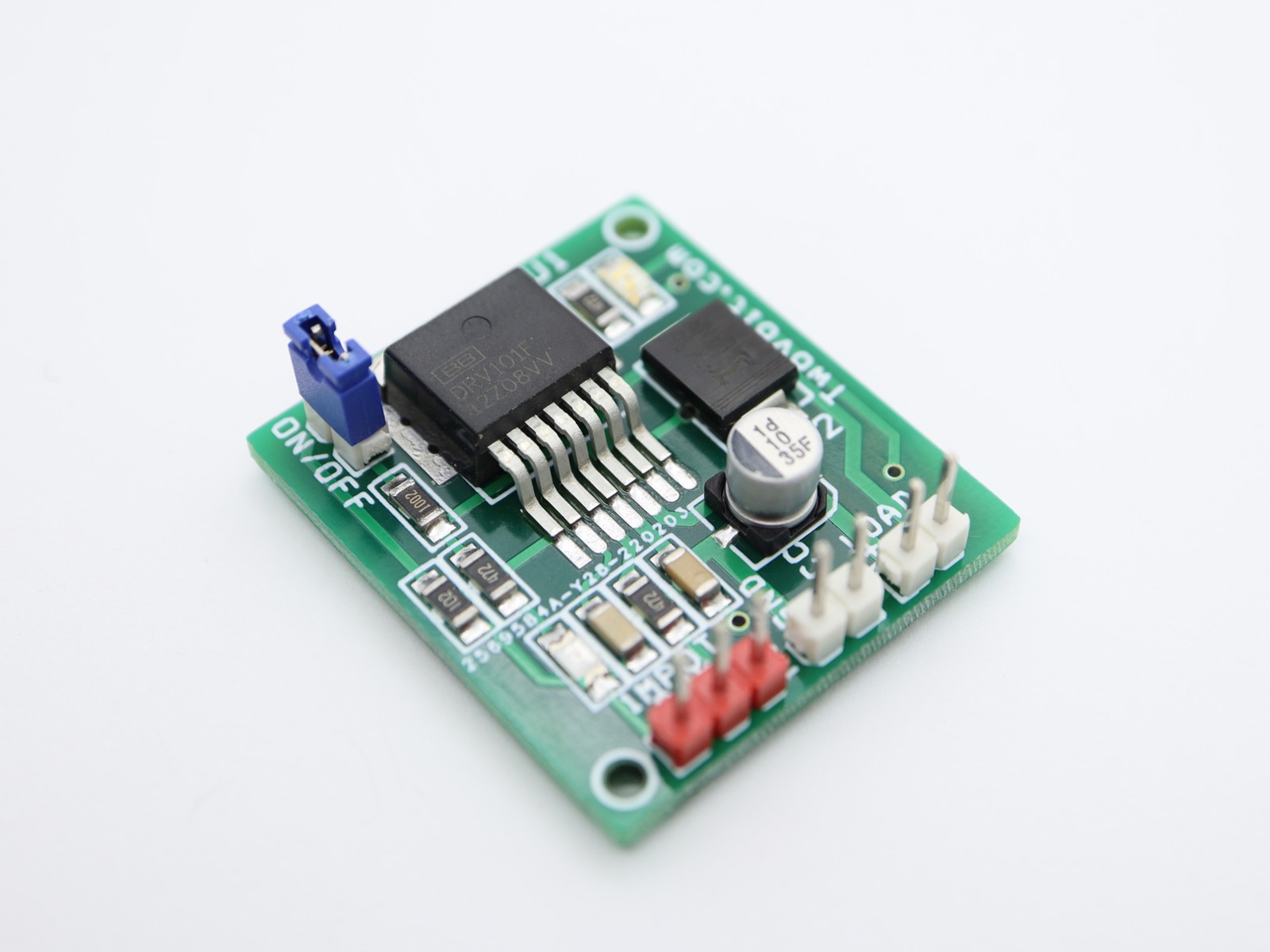
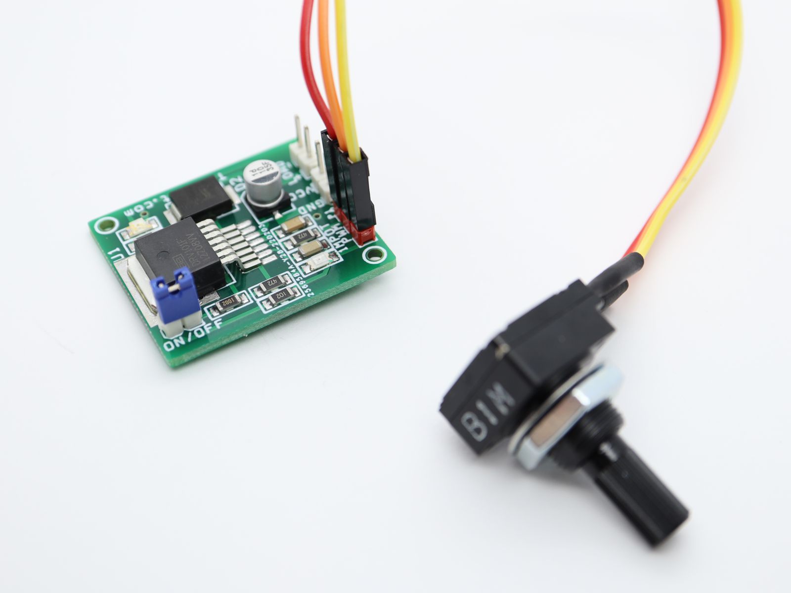
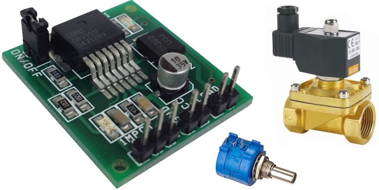
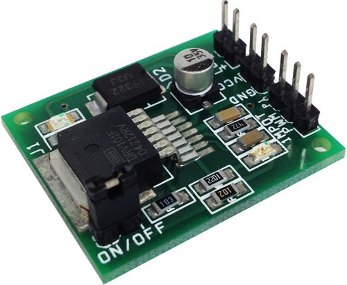
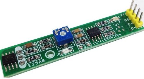
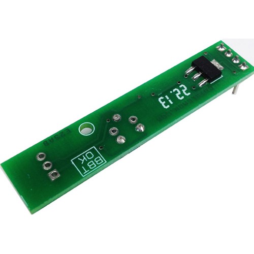
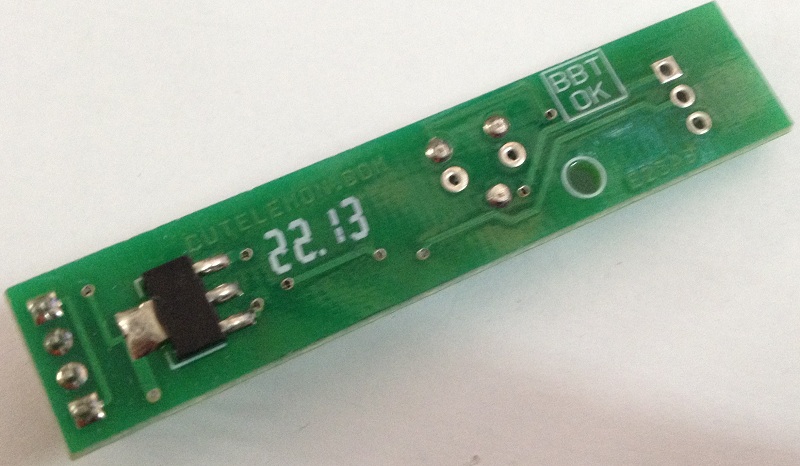
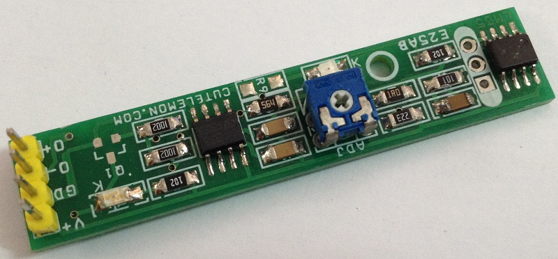
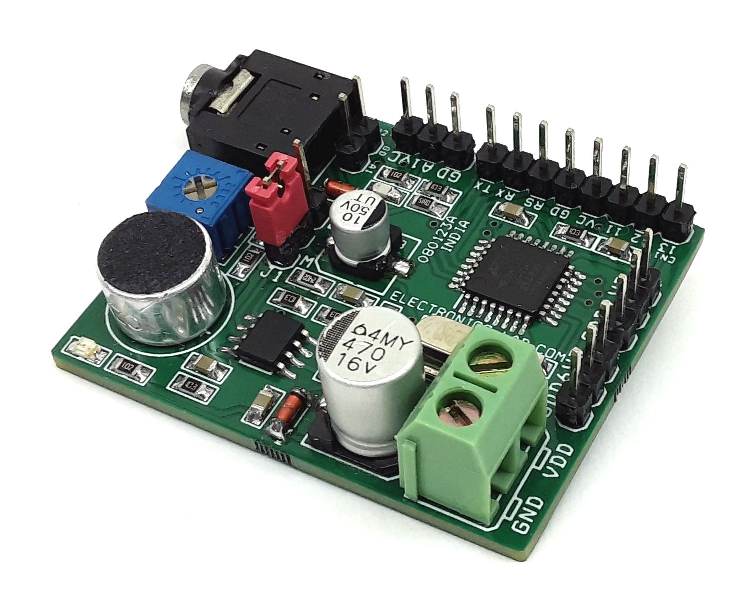
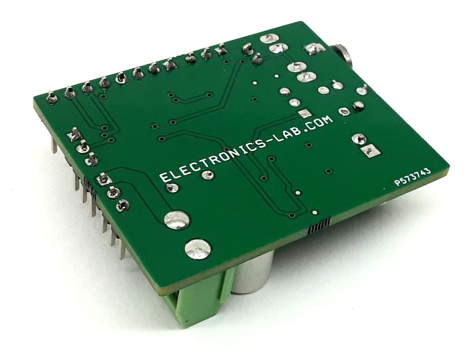
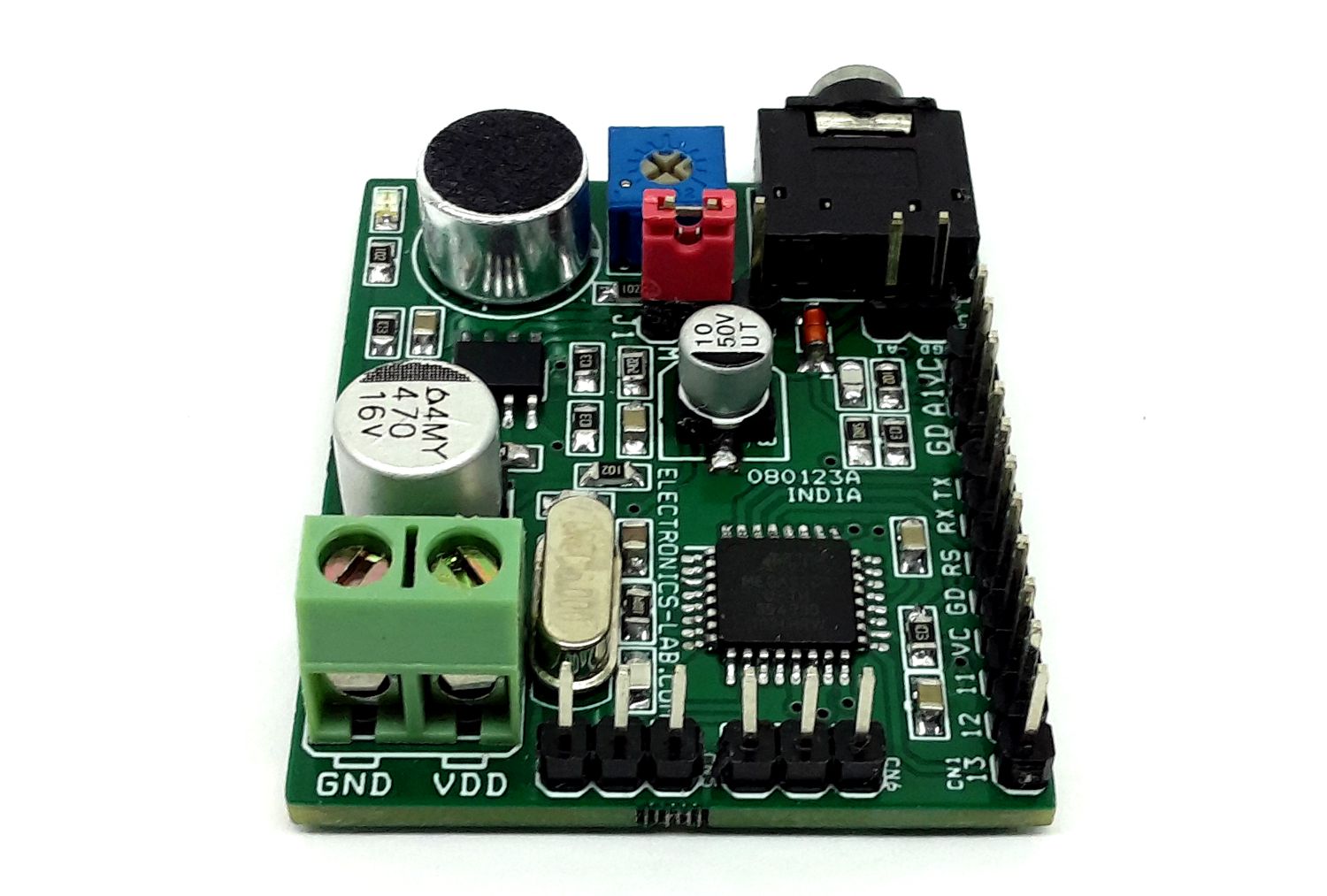
Photos
Video