Join the Community
Main Menu
Modos Flow is a 13.3-inch Open-Source 13.3-inch 60Hz E-Paper Monitor
Avalue EPC-WCL Fanless Edge AI System Packs Wildcat Lake SoC
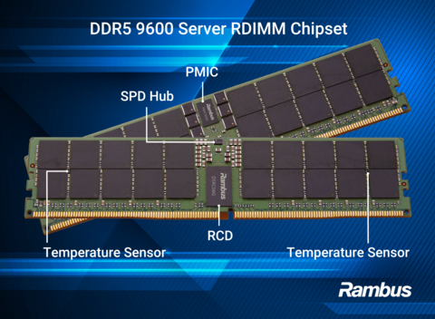
Rambus Debuts DDR5 9600 RDIMM Chipset for AI Servers
Qualcomm Snapdragon C Targets $300 Laptops with AI and All-Day Battery
The Approach to AI Infrastructure Is the Real Bubble
Mastering the Curve: Layout Strategies for FPC Bend Radius and Reliability
From Hearing to Understanding: MEMS Microphones as a Foundation of Robotic Perception
How to Clean a Soldering Iron Tip Without Ruining It
Analog To Digital Conversion - Sampling and Quantization
Positive Feedback in Electronic Circuits
Temperature Sensors
Magnetostatic Fields In Material Bodies
High Current Half Bridge with Over-Current Shutdown
3-Wire Electret Microphone Pre-Amplifier
12W Step Up DC-DC Converter using MAX1771
Sound to Light Color Shield for OLEDUINO v2
An Introduction to RF Theory, Practices, and Components: The Ins and Outs of RF
The Growing Decentralization of Power Grids
Designed for reading, writing, and development, this USB-C e-paper monitor is suitable for daily productivity.
Avalue EPC-WCL fanless system features Intel Core Series 3 (Wildcat Lake) processors, designed for industrial edge AI deployments.
A new registering clock driver pushes server memory to 9600 MT/s, targeting bandwidth-hungry agentic AI and HPC workloads.
Targeting the budget market, this highly efficient 6nm processor promises all-day battery life and integrated AI capabilities for...
A single-chip PMIC folds rotational-speed decoding into brake-by-wire voltage regulation, trimming parts count and board space in...
Powered by Rockchip RK3572, the new platform combines an octa-core CPU, 4 TOPS NPU, Linux 6.12 support, and extensive industrial...
ADLINK's COM-HPC Mini Module combines Intel Panther Lake processors, up to 64GB LPDDR5x, PCIe Gen5, USB4, and up to 180 TOPS AI...
New surface-mount polymer thermistors offer small footprints down to 0603, low resistance, and fast trip times for power delivery...
Powered by the RK3588S, the updated board features 8GB LPDDR5, 6 TOPS AI, NVMe support, dual MIPI-CSI, and a new dual analog...
This open-hardware screen leverages advanced FPGA capabilities to deliver fast refresh rates over USB Type-C, providing a responsive environment for...
A new non-volatile memory family offers four million cycles and hardware ECC for high-reliability data storage in demanding...
Powered by the CIX P1 processor, the Orange Pi 6 SBC combines 45 TOPS AI performance, dual 2.5GbE, LPDDR5 memory, and dual PCIe...