


")
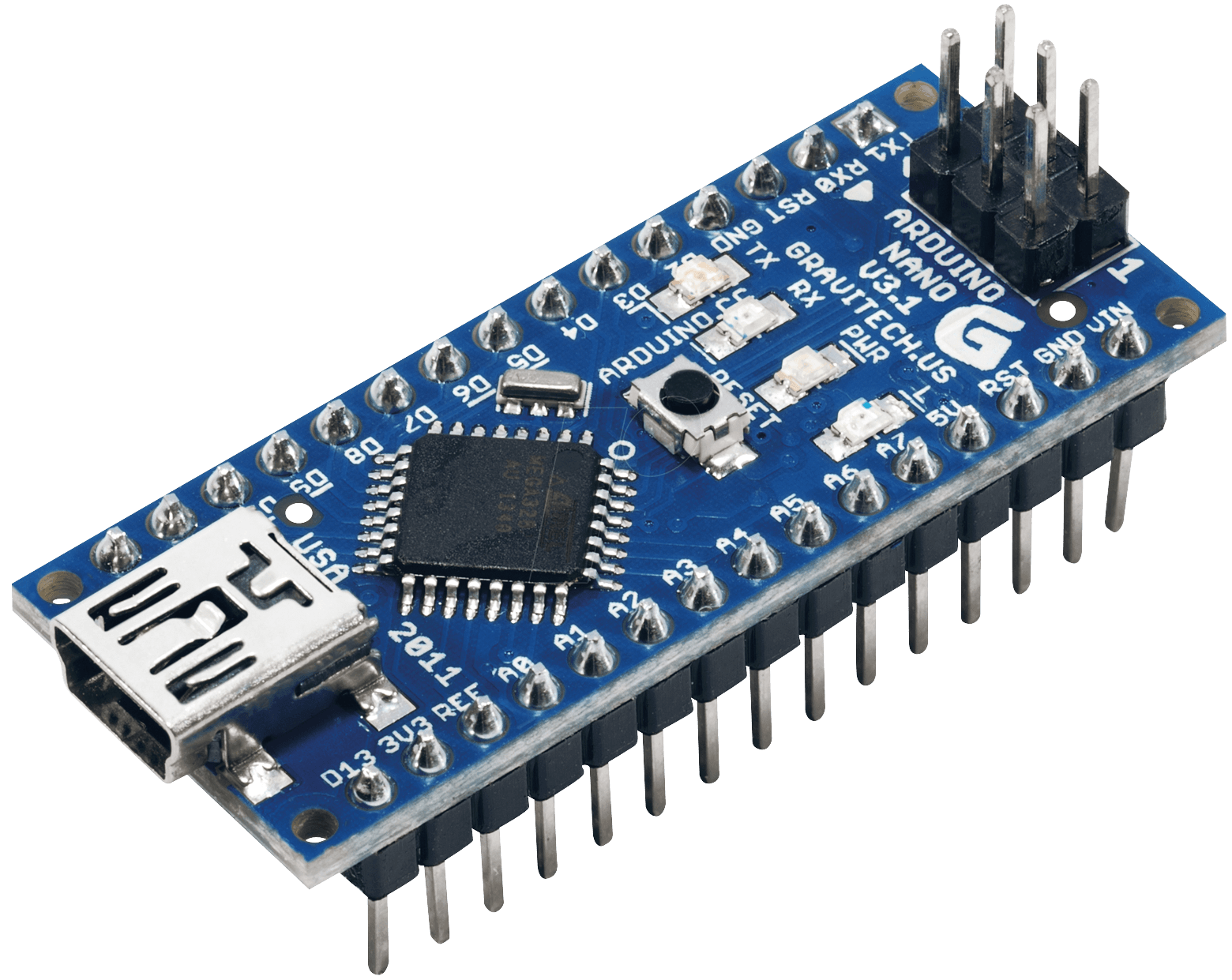
Make Your Own Arduino Nano In The Simplest Way (DIY – Arduino Nano)
In today’s post, we are going to learn how to make an Arduino nano at home. Electronics enthusiast Pratik Makwana designed this project in instructables.com. Every step in this project is well-explained. If you already don’t know what Arduino Nano is then here is a brief introduction: Arduino Nano is a tiny yet strong member of the Arduino family. It’s powered by an ATMega328P microcontroller running on 16MHz. But, the main strength is its very small form factor.
Now, let’s get started and make your own Arduino Nano in no time.
Requirements:
- Copper clad board (Double-sided)
- Ferric Chloride (FeCl3)
- Acetone (Nail polish remover)
- Glossy Paper
- LASER Printer
- Marker Pen
- Scissors
- Plastic container
- Sandpaper
- Safety gloves (Optional)
- Latex gloves
- Saw – For copper board cutting
- Laminator or iron
- Components of Arduino Nano (Given later)
PCB Designing:
This is a very important step of this tutorial. You need to draw the circuit of Arduino Nano first. Then you’ll design the PCB using the schematic. Design the schematic diagram in an EDA tool (Electronic design automation Software).
Here is a list of EDA Tools:
- DipTrace
- EAGLE PCB Design
- Kicad EDA
- Express PCB
- Proteus PCB Design & Simulation software
- Altium Designer
- NI Multisim
EAGLE is the most widely used PCB and schematic design software. Though my personal favorite is Proteus. You can use any software from the list.
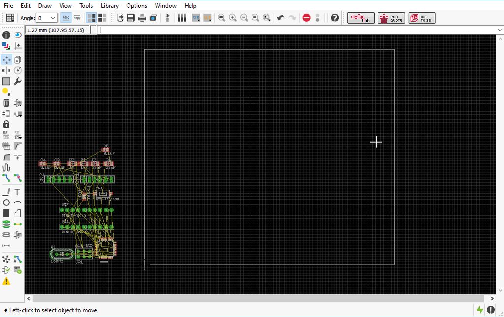
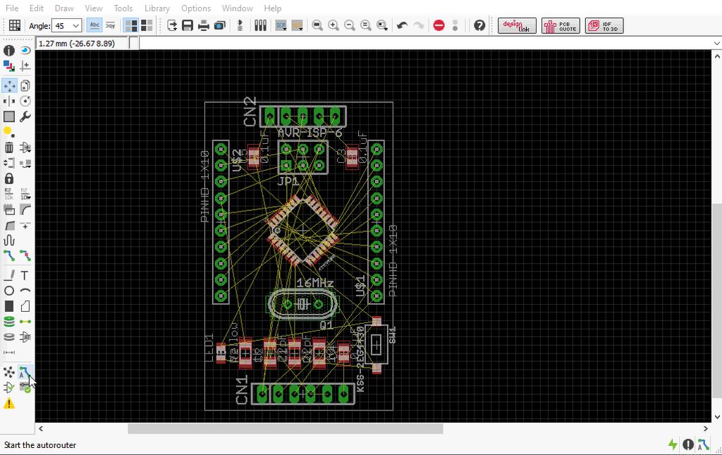
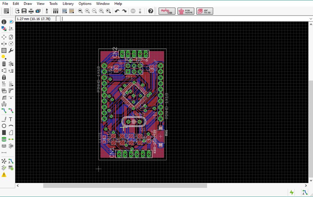
To make the schematic, use the Arduino Nano Circuit Diagram and Arduino Nano Components List. Once it’s drawn completely, open the PCB designing part of the software and you’ll see that schematic is imported there. Now place the components in correct places and connect them using traces. If you are using EAGLE then you can simply download the Arduino Nano Schematic File for EAGLE and Arduino Nano PCB File for EAGLE. Open the .brd file (PCB file) to print the PCB. You can also modify it if you wish.
Note:
- Use Only Laser printer only.
- Use glossy papers to print.
- Set scale factor to 1.
- Before top layer printing, you need to mirror the image of the top layer layout.
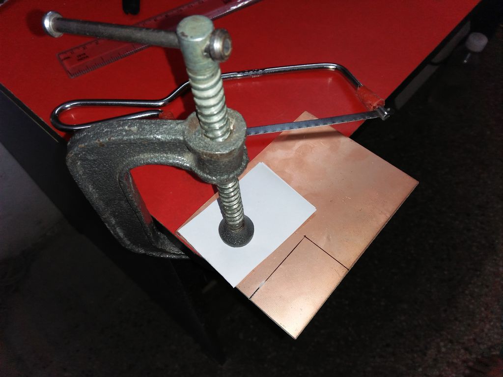
Cut The Copper Clad Board:
Now, cut the copper clad board according to the dimensions of the PCB. You can use a hacksaw to cut it off. Be precise about the dimensions. If it’s smaller than the actual PCB then you have to do it again. Also, cut the printed glossy paper as per the size of PCB.
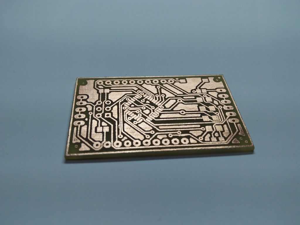
Toner Transfer and Etching Process:
In this step, the PCB design from glossy paper will be transferred to the copper board. All you need to do is place the printed side of the glossy paper on the copper board and apply both pressure and heat. You can use a modified laminator machine or an iron for this purpose. Why “modified”? Because toner transfer method requires a temperature of 210°C, where a laminator can provide 150°C maximum.
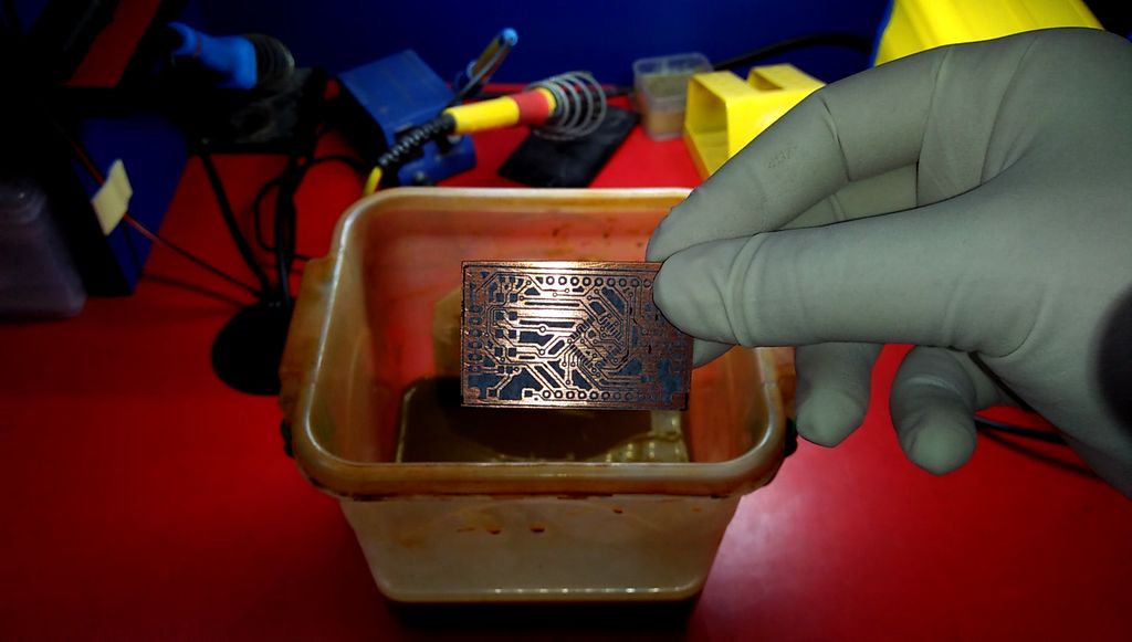
Make your copper clad board as clean as possible beforehand. You can use sandpaper and alcohol to do this. When the toner is transferred successfully, prepare the ferric chloride (FeCl3) solution. Before putting the board into the solution check carefully for any broken path. If found, draw it with a marker. After the etching process, use the acetone to clean the board.
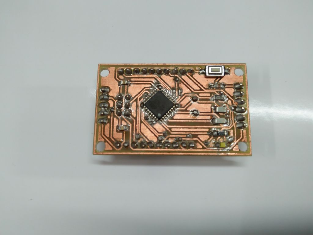
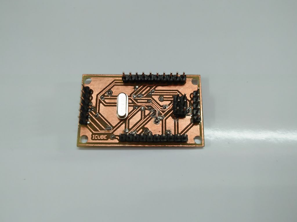
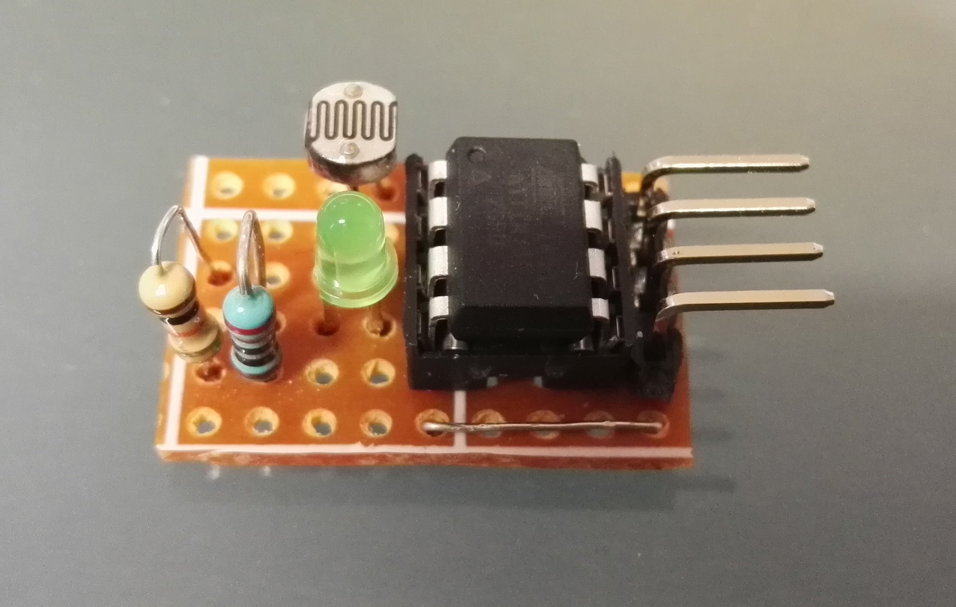
Drilling & Soldering:
Drill the PCB using PCB drill machine. Choose the drill bit wisely else components may not fit. Now, place the components on the PCB and solder them. You can use a helping hand device to get it done nicely.
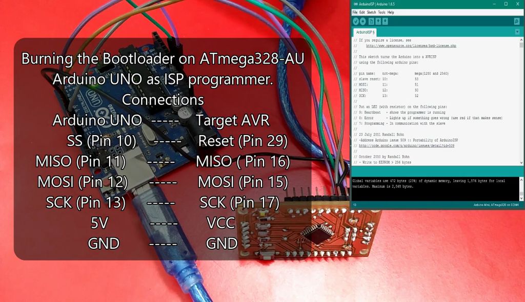
Burning The Arduino Bootloader:
In this step, you’ll need another Arduino board (e.g. Arduino UNO) to burn the bootloader to your newly made Arduino Nano for the first time. Open Arduino IDE and upload the ArduinoISP sketch to the Arduino UNO from examples option. Now, connect your Arduino Nano with Arduino UNO over SPI bus following the given instructions:
- Arduino UNO >> Arduino Nano
- ——————————————-
- SS (Pin 10) >> RESET (Pin 29)
- MISO (Pin 11) >> MISO (Pin 16)
- MOSI (Pin 12) >> MOSI (Pin 15)
- SCK (Pin 13) >> SCK (Pin 17)
- 5V >> VCC
- GND >> GND
After making the connections, go to Arduino IDE and follow the given instructions:
- Select Tool >> Board >> Arduino Nano
- Select Tool >> Port >> Select your Arduino UNO COM Port
- Select Tool >> Programmer >> Arduino as ISP
- Select Tool >> Burn Bootloader
Wait for the “Done burning bootloader” message to appear.
Testing:
Well, your Arduino Nano is now ready for a test run. This time you won’t need another Arduino to upload codes. Follow the instructions and connect a USB to TTL converter (a.k.a USB to UART converter) with the Arduino nano to upload sketches.
- USB to TTL Converter (CP2102) >> Arduino Nano
- —————————————————————-
- VCC >> VCC
- TX >> RX (Pin 30)
- RX >> TX (Pin 31)
- DTR >> RESET (Pin 29)
- GND >> GND
- After making the connections, go to Arduino IDE and perform the following tasks:
- Select File >> Examples >> 01.Basics >> Blink
- Select Tool >> Board >> Arduino Nano
- Select Tool >> Port >> Select your Arduino UNO COM Port
- Select Tool >> Programmer >> AVRISP MKII
After that, upload Blink Sketch to Arduino Nano and wait for the “Done Uploading” message. LED connected to pin 13 should blink if everything is OK. Now you can upload any sketch you wish to your home made Arduino Nano.
Conclusion:
So, this is how you can make your Arduino Nano. All you need for this project is PCB designing skills and a pretty good soldering skill as you have to deal with SMD components. This way you can make custom Arduino Nano that will fit your project perfectly. Watch the video to have a more clear idea:
RELATED POSTS
 9 November, 2016 Build Your Own I2C Sensor
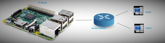 27 December, 2015 Setting Up Python web server for Raspberry Pi
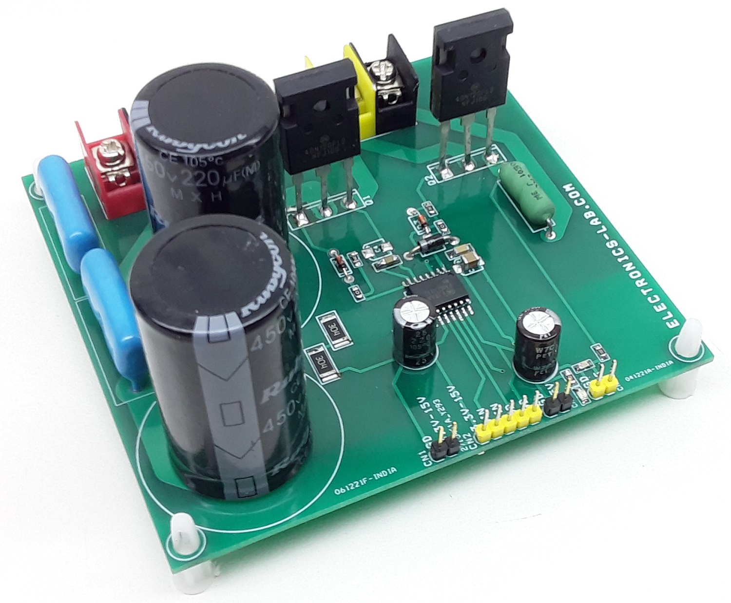 22 March, 2022 1200V High-Current Half-Bridge using FAN73912
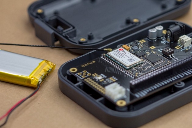 22 May, 2018 Particle E-Series Modules – LTE Connectivity designed for IoT
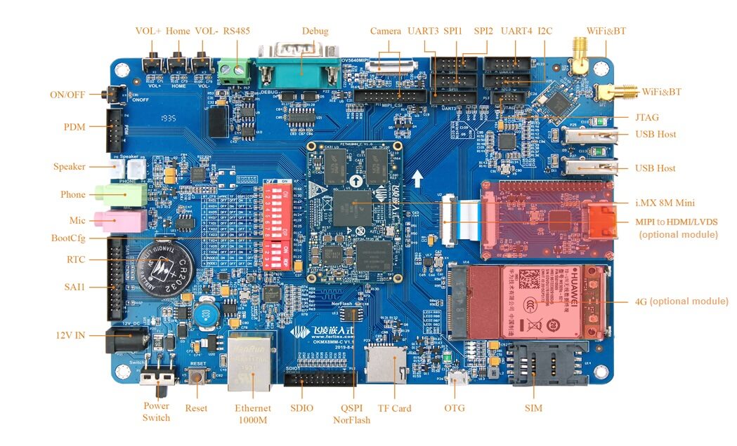 22 September, 2020 Forlinx FETMX8MM-C SoM for Optimized Audio Performance
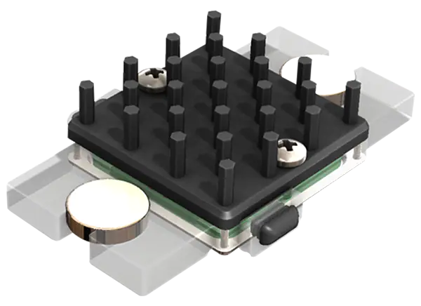 1 August, 2022 MATRIX Industries PRMT11-18305-30 Prometheus Energy Harvest Module


