


Making an electronic dice is very popular among hobbyists and there are already lots of ready-made projects on the internet about this topic. Tim at Hackaday.io designed an electronic dice project for “1KB Limit” competition. But why another dice project while the internet is already crowded with similar things?
Well, it’s not the subject of this project, but the concept, which makes it unique. This is the most miniaturized dice one can make. As Tim says:
It makes use of a very efficient multiplexing scheme to drive all the 7 LEDs of an electronic die with only two I/O pins.
Yes, you’ve read it right. Only two I/Os are used to control all 7 LEDs of a die. It became possible for a super-efficient multiplexing scheme – Charlieplex Plus. The main goal of this project is introducing you to Charlieplex Plus.
Requirements:
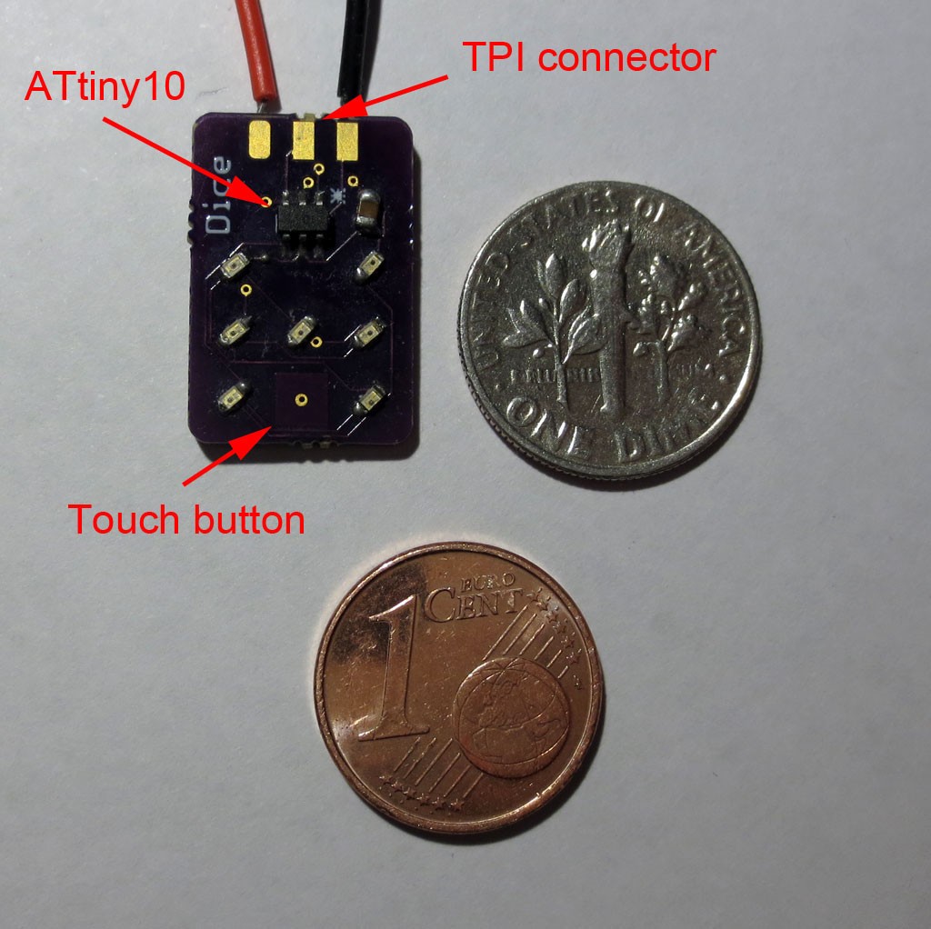
- 1 x ATtiny10
- 7 x SMD LED 0603
- 1 x SMD Capacitor 100n 0805
- PCB of the Circuit
Please Note: SMD components are used to miniaturize the circuit. You can easily go for through-hole components if size is not a concern.
Important Links:
- dice10.gif – A moving image of the circuit
- TinyTouch Library – Download the touch library from GitHub
- MagicDice_v1.2.brd – The board file of this project
- MagicDice_v1.2.sch – The schematic file of this project
Circuit and PCB:
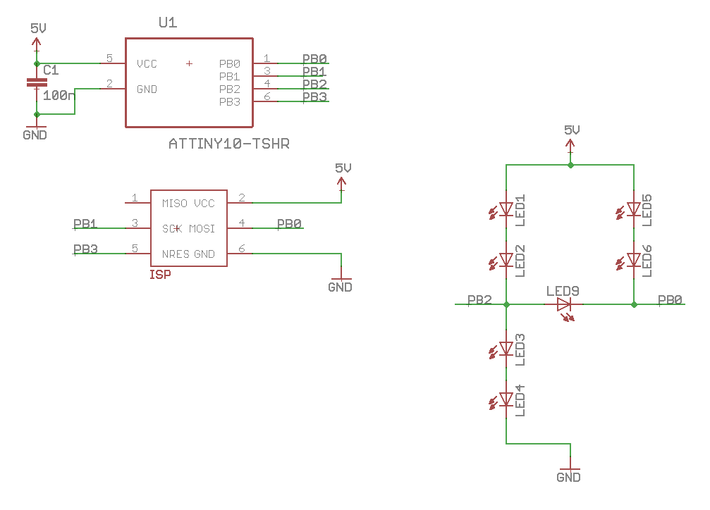
You can see from the circuit that connections are pretty straight forward. PB2 and PB0 are used to drive the LEDs. The remaining free I/O pin, PB1, is used as a touch sensor. PB1 is RESET pin, so it can’t be used as GPIO.
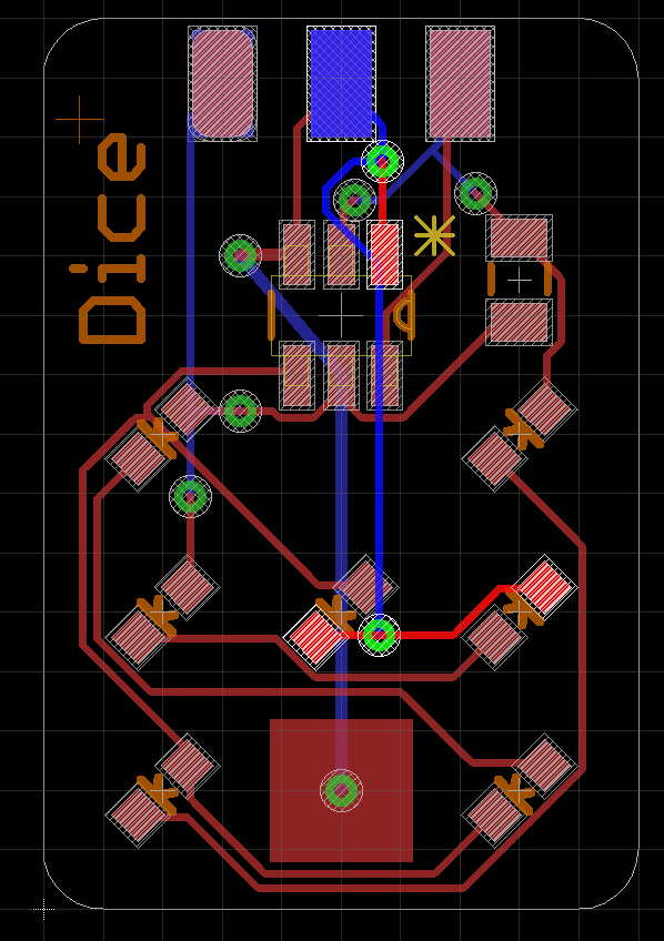
All components are squeezed into a PCB that is only 13 mm x 19 mm. Instead of 6 pin headers, edge connections are used for SPI/TPI interface in order to reduce the PCB size.
Design:
As an entry for Hackaday 1Kb competition, one vital target of this project was to keep the code size below 1Kb. Using an ATtiny10 as an MCU automatically limits the code size to 1kb, so the requirement is automatically met.
The firmware uses a timer interrupt to multiplex all the 7 LEDs. The main routine calls the TinyTouchLib to poll the touch button. If a button press is detected, the value of the die is changed in a random manner. Though due to smaller physical size, the touch button is somewhat unreliable and often detects multiple touches. But there is no problem in using it as a random number generator.
Multiplexing:
Now coming to the most interesting part of the design – the multiplexing scheme. A very common and efficient scheme is Charlieplexing. Impleneting charlieplexing you can control n²-n LEDs by n I/O lines.
Now, how can you control 7 LEDs of the die using only 2 I/O pins?
The dice pattern consists of 7 LEDs. However, you will quickly notice that 6 of these LEDs only light up in pairs, so that only 3 pairs of LEDs plus the middle one need to be controlled. This requires four I/Os – still too much!
Using Charlieplexing we can reduce the number of I/O lines to three. but still a bit too much for the ATtiny10, as an extra I/O line is required to “roll the die”. The only solution left is “Charlieplex Plus”. Before explaining that, let’s learn what Charlieplexing is.
Charlieplexing: Charlieplexing is a technique for driving a multiplexed display in which relatively few I/O pins on a microcontroller are used to drive an array of LEDs. Charlieplexing uses the tri-state property (neither HIGH nor LOW state) of microcontroller I/O pins. Only two I/Os are active at a time – one set to HIGH and one set to LOW – while all other pins are in a high resistivity state. LED connected between two active I/Os will light up.
Now, what if we activate only one I/O instead of two? Here comes Charlieplex Plus.
Charlieplex Plus:
The circuit above shows how to connect LEDs in this scheme. In addition to the antiparallel pair between the two I/O pins (PB2 and PB0), LEDs are also connected to VCC and GND. The sum of forward voltages of the four LEDs in series (LED1-4 and LED5-8) is higher than 5V so that they will not light up when PB0 and PB2 are in the high impedance (Z) state.
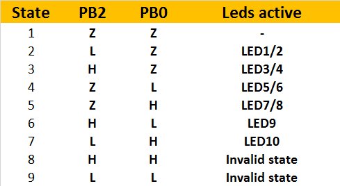
When either PB0 or PB2 is H or L and all other pins are Z, sufficient voltage is present to light up a pair of LEDs. However, when PB0 is HIGH and PB2 is LOW or vice versa, LED9 or LED10 will light up.
In fact, Charlieplex plus scheme is really hard to understand. It is impractical as well. But it’s still usable in such cases where our only option is to control lots of LEDs with lesser I/Os. Let’s look at the table to have a better understanding:
A general analysis shows that the new scheme can drive n²+n LEDs with n I/Os. The table below shows the number of LEDs than can be driven with a given number of I/Os with different multiplexing schemes.
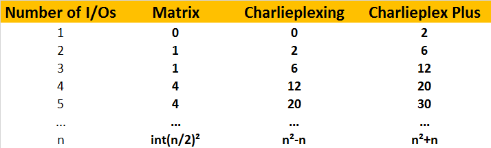
So, in a summary, we can see that two I/Os are capable of handling three LEDs, and that’s what we need.
Conclusion:
In this article, the multiplexing scheme was the first priority. If you understand the scheme clearly, you can implement it in different projects. Read this blog post if you are willing to learn more on this.
This image shows how the DICE10 works:
But remember that implementing Charlieplex Plus in any project is not recommended at all. It’ll make the design and the troubleshooting process extremely complex.
RELATED POSTS
 31 August, 2015 50,000V High Voltage Power Supply
 15 December, 2020 High voltage Half-Bridge with Current Feedback using L6390
 10 February, 2020 Toshiba launches new high-resolution micro-stepping motor driver IC with integrated current sensing
 10 April, 2018 Broadcom AFBR-S50 ToF laser light sensor measures up to 10 meters
 26 May, 2022 LEM to unveiled the world’s first Integrated Current Sensor with Sigma Delta bitstream output
 14 July, 2020 Arduino Adds Four New Boards To The Ardunino Nano Family


