Prasad Pandit @ youtube.com:
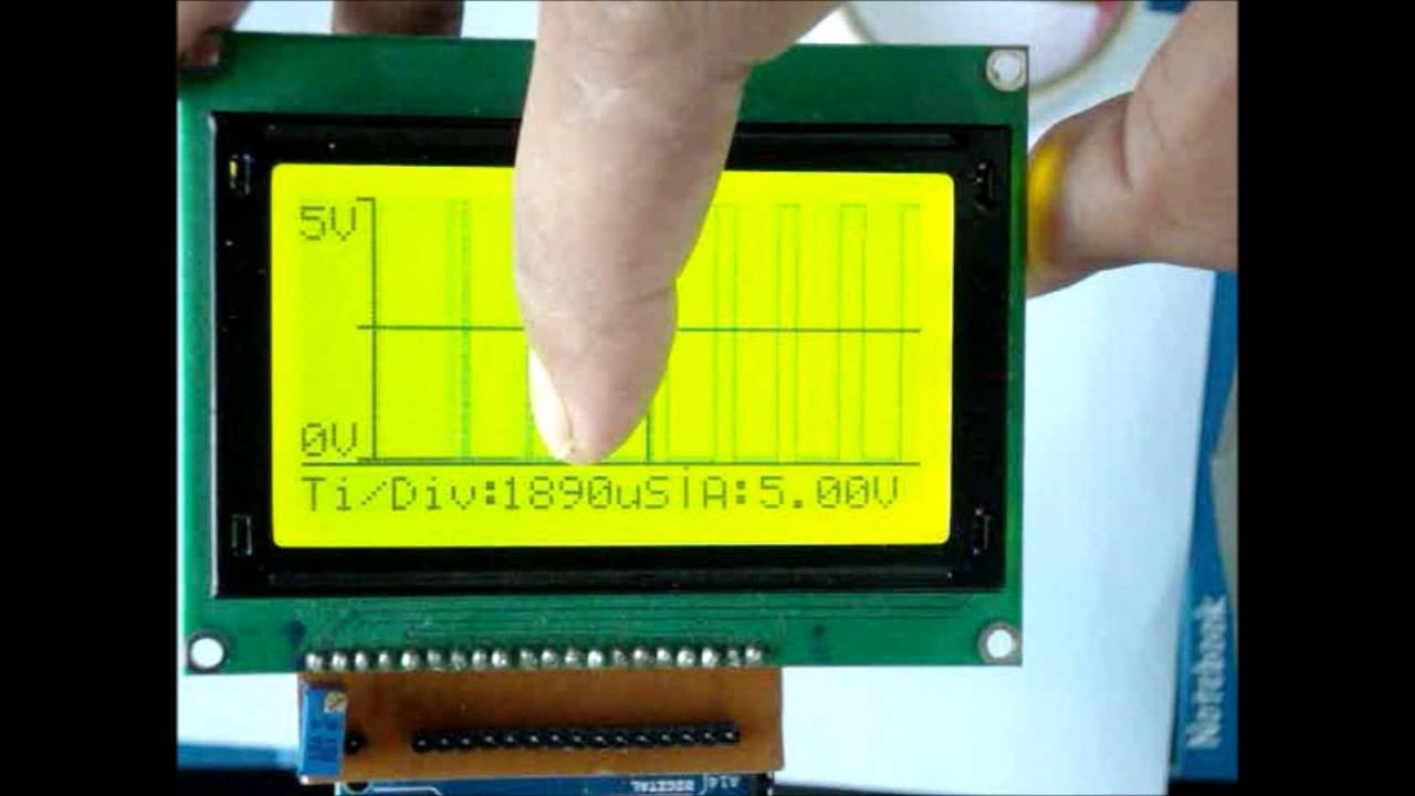
I have designed an Oscilloscope using Arduino Mega 2560 and 128×64 GLCD. It works pretty good for verification of signal the range of input frequency is upto 10-12MHz and Sampling rate is 200KSPS. It has no Attenuation so you will have to convert highvoltage signal to 5 v pTp signal. And yes for Sine wave or Cos wave or signal which is below ground voltage you will have to DC shift the signal. You can set the Time/Division for studying signal. It gives Peak to Peak voltage value of signal in Real Time till two decimals.
All the Arduino GLCD libraries used are freely available. If you have suggestions mail me on: prasadp4009@gmail.com
Code Link: www.dropbox.com
DIY Oscilloscope using Arduino and Graphic LCD – [Link]




link code error
Link updated. Thanks for letting us know.
greeatings
i need a code for lcd 128×64, your library not is funcional, your library have a problem for compilation in adruino mega
Interesting project, but dude – Stop asking “OK?” during the video – As if we could answer… Pfft…
Not trying to be rude or anything, but it’s annoying having to listen to it.
Also, try to brush up on your accent and try to articulate abbreviations better. “PWM” sounded like a short humming-rhythm.