OMZLO Programs the new TinyAVR MCUs
OMZLO has posted details about baremetal programming on the new TinyAVR MCUs. In their blog post, they describe how to program a blinky firmware on an Attiny406, from the ground up, using the simplest tools.
OMZLO has posted details about baremetal programming on the new TinyAVR MCUs. In their blog post, they describe how to program a blinky firmware on an Attiny406, from the ground up, using the simplest tools. Most of the things described can be easily transposed to other TinyAVR MCUs. About the programming, they say:
“Our approach is generally guided toward macOS or Linux users, but should also be applicable in an MS-Windows environment with a few minor changes.”
Even though OMZLO has been mainly focussing their development efforts on newer 32-bit Arm-Cortex chips (STM32 and SAMD), which typically offer more RAM, more speed, more peripherals, at a similar or lower price-point than older 8-bit MCUs, they decided to use the 8-bit MCUs which are substantially simpler to program.
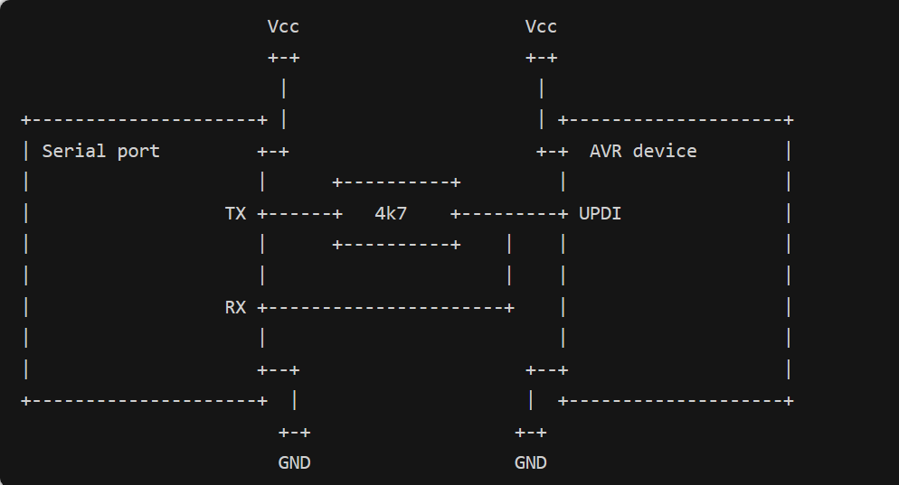
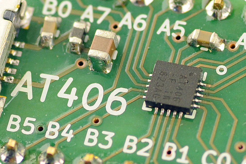
Regarding the hardware, they decided to work with the Attiny406, with a view of using it in the future to replace the Attiny45 they currently use on the PiWatcher, which is their Raspberry-Pi watchdog. The Attiny406 enables 4K of flash space, 256 bytes of RAM, and can run at 20Mhz without an external clock source. We should note that one of the most important differences between the new TinyAVR MCUs and the older classic AVR MCU like the Attiny85 is that the newer chips use a different programming protocol called UPDI, which requires only 3 pins, as opposed to the 6-pin ISP on the classic AVRs. A little research shows that programming TinyAVRs with UPDI can be achieved with a simple USB-to-serial cable and a resistor, thanks to a python tool called pyupdi.
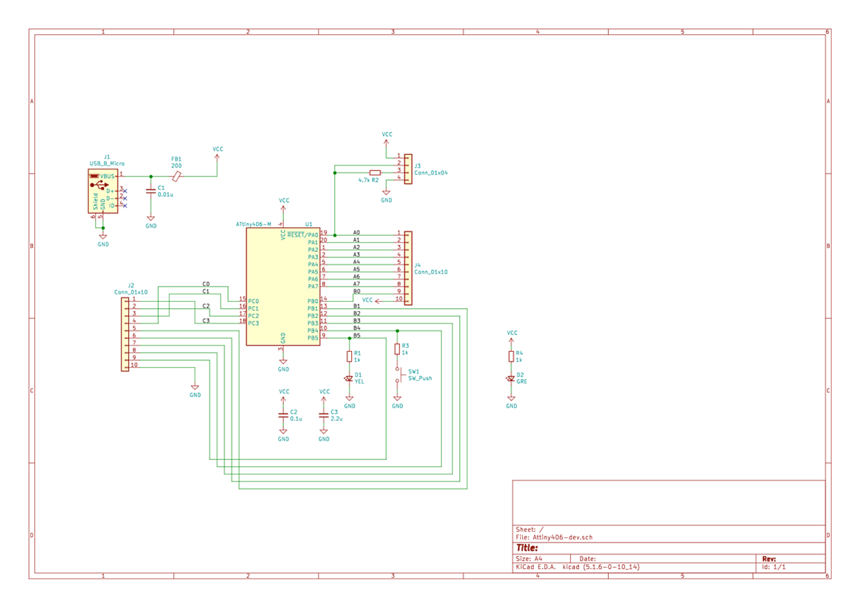
For the schematic, they created a minimalistic breakout board for the Attiny406. The board can be powered by 5V through USB or a lower 3.3V through dedicated VCC/GND pins. They also equipped the board with LED and a button was also fitted on the board, and for testing purposes, they decided to embed the 4.7K resistor needed for the UPDI programming directly in the hardware (i.e. resistor R2). The resulting breakout board is tiny and fits conveniently on a small breadboard. The design files are shared on aisler.net. When you want to Program the Attiny406 on the board with a USB-serial cable, you just connect the headers on the board edge.
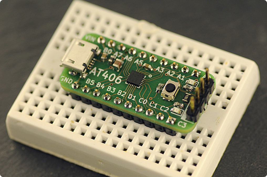
For software, they installed pyupdi following the instructions provided on their webpage. They also connected the USB-Serial cable to the board with the 4 dedicated UPDI pins available on the board. After installing the software, the USB-Serial converter shows up as the file /dev/tty.usbserial-FTF5HUAV on a MacOS system. To test that the programmer recognizes the Attiny406, you can issue a command similar to the following, adapting the path for the USB-serial converter to your setup: pyupdi -d tiny406 -c /dev/tty.usbserial-FTF5HUAV -i This should result in the following output if all goes well: Device info: {‘family’: ‘tinyAVR’, ‘nvm’: ‘P:0’, ‘ocd’: ‘D:0’, ‘osc’: ‘3’, ‘device_id’: ‘1E9225’, ‘device_rev’: ‘0.1’}
With the right tools, bare-metal programming on the new TinyAVR MCUs is as simple as on its older AVR cousins. You can find more information on OMZLO’s blog post. If you have programming tips for the AVRTiny, you can also share it with them on Twitter.


