Recover Bricked ATtiny Using Arduino as high voltage programmer
Hi! Today I'll explain you how to recover your bricked ATtiny microcontroller using your Arduino board.
Hi! Today I’ll explain you how to recover your bricked ATtiny microcontroller using your Arduino board. ATtinys are very popular due to their small form factor yet very powerful. While working with them you may accidentally brick the ATtiny. As arduino is extremely popular and really easy to use, I guess you have one or more lying on your work table. You don’t need to purchase a HVP (High Voltage Programmer), or search for an old PC with parallel port to recover ATtiny. Just build a small circuit, plug it into Arduino board, upload a sketch and you are good to go. So let’s start…
HOW ATTINY CAN BE BRICKED?
Actually, there are many reasons. But let me explain what I mean by “bricked”. If you’ve powered it with over voltage and fried it, well, it’s not “bricked” then, rather it’s roasted. Arduino and HVP have nothing to do with it. But, if your ATtiny stopped responding due to some wrong fuse settings, then it’s “Bricked” and hopefully we can recover it using Arduino as HVP. So another question is, what is fuse settings? Well, there are 3 bytes of permanent (by permanent I mean that they stick around after power goes out, but that you can change them as many times as you’d like) storage called the fuses. The fuses determine how the chip will act, whether it has a bootloader, what speed and voltage it likes to run at, etc. Note that despite being called ‘fuses’ they are re-settable and don’t have anything to do with protection from overpowering.
To learn more about fuses, simply google about AVR fuse. Or you may check this article .
There are various mistakes one can make in fuse settings that result in a bricked ATtiny. Most common of them are Disabling ISP Programming and Selecting Wrong Clock Source. If ISP programming is disabled in fuse settings, ATtiny will not respond to an ISP Programmer. It’s just like, you have a robot that does exactly what you order him and one day you order him “Stop listening to me!”. You know what’ll happen.
And if you set fuses that select wrong clock source than you are actually providing, it will stop responding until correct clock source is provided as per fuse settings which you either don’t know or forgot.
In these situations we can say ATtiny is “Bricked”.
HOW TO RECOVER IT?
Okay, now we need to learn how we can recover our ATtiny from bricked state. As we’ve already learned, ISP programmer can do nothing anymore until fuses are reset in default mode, hence we need a High Voltage Programmer. If you want to know how a HVP works, google about it.
Here we’ll make a High Voltage programmer using Arduino. Arduino has more than enough pins to simulate a HVP. A very minimal additional circuitry is required.
We’ll make the circuit, plug it in to Arduino, Upload sketch in Arduino and we are good to go. The HVP will reset the fuses of ATtiny to default one. So, the ATtiny will again respond to ISP programmer.
Considering you already have Arduino, the cost of rest of the circuitry will be very small.
THINGS YOU NEED
To make the circuit on breadboard, you’ll need the following parts:
- A breadboard
- An Arduino Uno (any Arduino should work fine)
- A 2N2222A transistor (Any NPN transistor should do)
- 6 x 1K resistor
- Some jumper wires
- A 12V power supply @ 500mA.
- If you don’t have 12V source, you may use a boost converter. 5V to 12V converter is a good choice. [PURCHASE LINK]
If you want to make it on vero board or PCB, use an 8 pin IC base (DIL08) and L shaped male header (7 pins required). Making a permanent board is recommended.
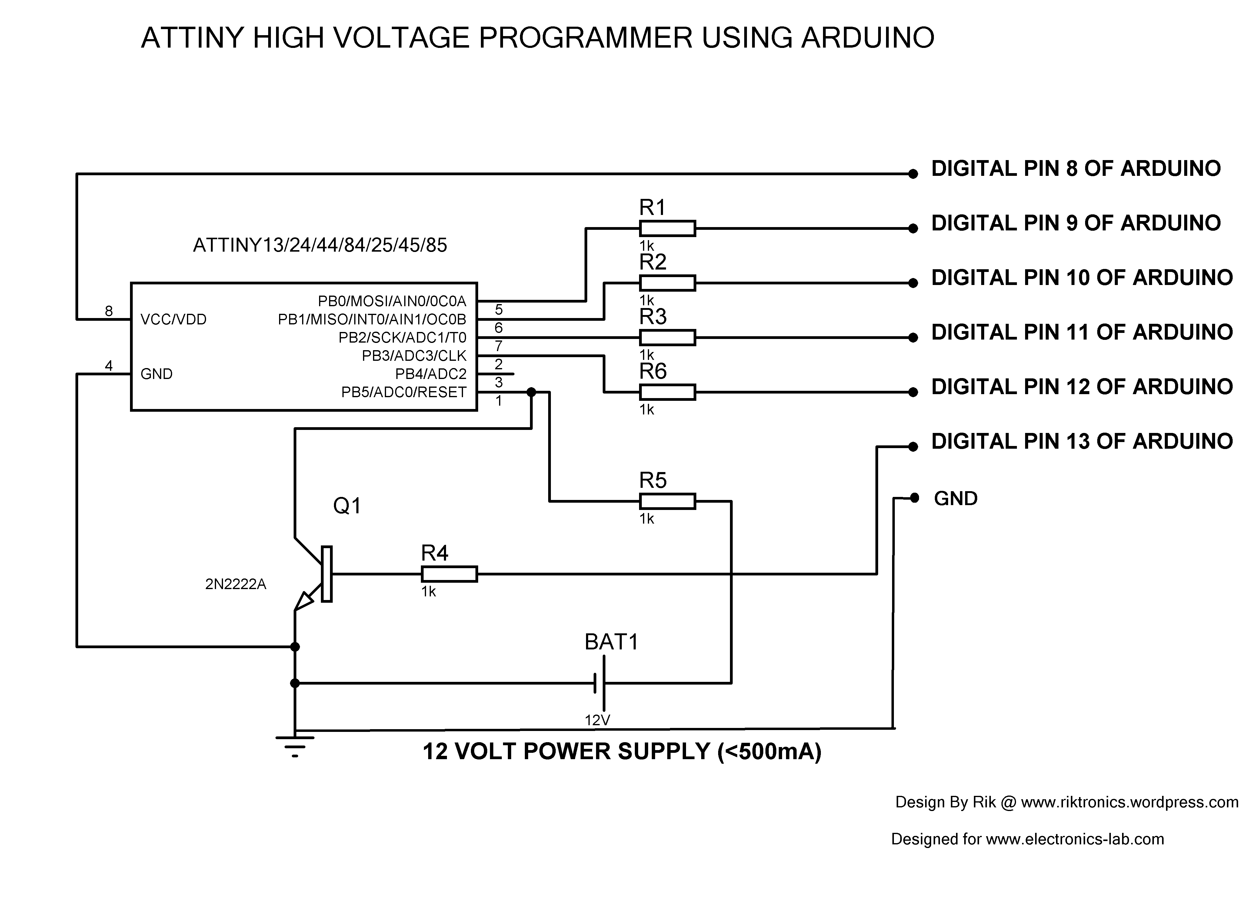
CIRCUIT DIAGRAM
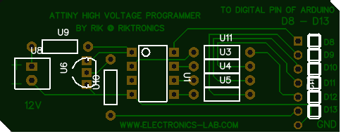
PCB LAYOUT
Use below pdf files to etch your own PCB on copper clad. There are 2 pdfs in .zip file. Consult both of them to get idea about orientation of components. Print the pdf in MIRROR view to get correct orientation after etching.
attiny-hv-programmer-PDF PCB LAYOUT-rik
Below pdf is for colored PCB layout. You may not need it.
attiny-hv-programmer-PCB COLORED-rik
Use below Gerber files to fabricate PCB.
attiny_hv_programmer_GERBER FILE_rik
The following image shows how the PCB looks like:
ARDUINO SKETCH
 // AVR High-voltage Serial Fuse Reprogrammer
 // Adapted from code and design by Paul Willoughby 03/20/2010
 // http://www.rickety.us/2010/03/arduino-avr-high-voltage-serial-programmer/
 // Fuse Calc:
 // http://www.engbedded.com/fusecalc/

 #define RST 13 // Output to level shifter for !RESET from transistor
 #define SCI 12 // Target Clock Input
 #define SDO 11 // Target Data Output
 #define SII 10 // Target Instruction Input
 #define SDI 9 // Target Data Input
 #define VCC 8 // Target VCC

 #define HFUSE 0x747C
 #define LFUSE 0x646C
 #define EFUSE 0x666E

 // Define ATTiny series signatures
 #define ATTINY13 0x9007 // L: 0x6A, H: 0xFF 8 pin
 #define ATTINY24 0x910B // L: 0x62, H: 0xDF, E: 0xFF 14 pin
 #define ATTINY25 0x9108 // L: 0x62, H: 0xDF, E: 0xFF 8 pin
 #define ATTINY44 0x9207 // L: 0x62, H: 0xDF, E: 0xFFF 14 pin
 #define ATTINY45 0x9206 // L: 0x62, H: 0xDF, E: 0xFF 8 pin
 #define ATTINY84 0x930C // L: 0x62, H: 0xDF, E: 0xFFF 14 pin
 #define ATTINY85 0x930B // L: 0x62, H: 0xDF, E: 0xFF 8 pin

 void setup() {
 pinMode(VCC, OUTPUT);
 pinMode(RST, OUTPUT);
 pinMode(SDI, OUTPUT);
 pinMode(SII, OUTPUT);
 pinMode(SCI, OUTPUT);
 pinMode(SDO, OUTPUT); // Configured as input when in programming mode
 digitalWrite(RST, HIGH); // Level shifter is inverting, this shuts off 12V
 Serial.begin(19200);
 Serial.println("Code is modified by Rik. Visit riktronics.wordpress.com and electronics-lab.com for more projects");
 Serial.println("-------------------------------------------------------------------------------------------------");
 Serial.println("Enter any character to start process..");}


 void loop() {
 if (Serial.available() > 0) {
 Serial.read();
 pinMode(SDO, OUTPUT); // Set SDO to output
 digitalWrite(SDI, LOW);
 digitalWrite(SII, LOW);
 digitalWrite(SDO, LOW);
 digitalWrite(RST, HIGH); // 12v Off
 digitalWrite(VCC, HIGH); // Vcc On
 delayMicroseconds(20);
 digitalWrite(RST, LOW); // 12v On
 delayMicroseconds(10);
 pinMode(SDO, INPUT); // Set SDO to input
 delayMicroseconds(300);
 unsigned int sig = readSignature();
 Serial.println("Reading signature from connected ATtiny......");
 Serial.println("Reading complete..");
 Serial.print("Signature is: ");
 Serial.println(sig, HEX);
 readFuses();
 if (sig == ATTINY13) {

 Serial.println("The ATtiny is detected as ATtiny13/ATtiny13A..");
 Serial.print("LFUSE: ");
 writeFuse(LFUSE, 0x6A);
 Serial.print("HFUSE: ");
 writeFuse(HFUSE, 0xFF);
 Serial.println("");
 } else if (sig == ATTINY24 || sig == ATTINY44 || sig == ATTINY84 ||
 sig == ATTINY25 || sig == ATTINY45 || sig == ATTINY85) {

 Serial.println("The ATtiny is detected as ");
 if(sig == ATTINY24) Serial.println("ATTINY24..");
 else if(sig == ATTINY44) Serial.println("ATTINY44..");
 else if(sig == ATTINY84) Serial.println("ATTINY84..");
 else if(sig == ATTINY25) Serial.println("ATTINY25..");
 else if(sig == ATTINY45) Serial.println("ATTINY45..");
 else if(sig == ATTINY85) Serial.println("ATTINY85..");

 writeFuse(LFUSE, 0x62);
 writeFuse(HFUSE, 0xDF);
 writeFuse(EFUSE, 0xFF);
 }

 Serial.println("Fuses will be read again to check if it's changed successfully..");
 readFuses();
 digitalWrite(SCI, LOW);
 digitalWrite(VCC, LOW); // Vcc Off
 digitalWrite(RST, HIGH); // 12v Off

 Serial.println("");
 Serial.println("");
 Serial.println("");
 Serial.println("");
 }
 }

 byte shiftOut (byte val1, byte val2) {
 int inBits = 0;
 //Wait until SDO goes high
 while (!digitalRead(SDO))
 ;
 unsigned int dout = (unsigned int) val1 << 2;
 unsigned int iout = (unsigned int) val2 << 2;
 for (int ii = 10; ii >= 0; ii--) {
 digitalWrite(SDI, !!(dout & (1 << ii)));
 digitalWrite(SII, !!(iout & (1 << ii)));
 inBits <<= 1; inBits |= digitalRead(SDO);
 digitalWrite(SCI, HIGH);
 digitalWrite(SCI, LOW);
 }
 return inBits >> 2;
 }

 void writeFuse (unsigned int fuse, byte val) {

 Serial.println("Writing correct fuse settings to ATtiny.......");

 shiftOut(0x40, 0x4C);
 shiftOut( val, 0x2C);
 shiftOut(0x00, (byte) (fuse >> 8));
 shiftOut(0x00, (byte) fuse);

 Serial.println("Writing complete..");
 }

 void readFuses () {

 Serial.println("Reading fuse settings from connected ATtiny.......");

 byte val;
 shiftOut(0x04, 0x4C); // LFuse
 shiftOut(0x00, 0x68);
 val = shiftOut(0x00, 0x6C);
 Serial.print("LFuse: ");
 Serial.print(val, HEX);
 shiftOut(0x04, 0x4C); // HFuse
 shiftOut(0x00, 0x7A);
 val = shiftOut(0x00, 0x7E);
 Serial.print(", HFuse: ");
 Serial.print(val, HEX);
 shiftOut(0x04, 0x4C); // EFuse
 shiftOut(0x00, 0x6A);
 val = shiftOut(0x00, 0x6E);
 Serial.print(", EFuse: ");
 Serial.println(val, HEX);
 Serial.println("Reading complete..");
 }

 unsigned int readSignature () {
 unsigned int sig = 0;
 byte val;
 for (int ii = 1; ii < 3; ii++) {
 shiftOut(0x08, 0x4C);
 shiftOut( ii, 0x0C);
 shiftOut(0x00, 0x68);
 val = shiftOut(0x00, 0x6C);
 sig = (sig << 8) + val;
 }
 return sig;
 }
PROCEDURE
First of all make the circuit either on breadboard or on PCB/veroboard.
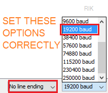
Now, connect your Arduino to PC and open ArduinoIDE. Select correct COM port. Write or copy-paste the given sketch to IDE and upload it to Arduino. Once uploaded successfully, go to serial monitor and set Baud rate to 19200 and No line ending.
Now, connect pins of the circuit you made to respective pins of Arduino. If you have made a PCB with L shape male headers, simply plug it in to Arduino’s D8-D13 (and GND) pins.
If serial monitor is opened already, close it. Reset Arduino by pressing reset button. Now re-open serial monitor. As soon as it’s opened, you’ll see the following message:
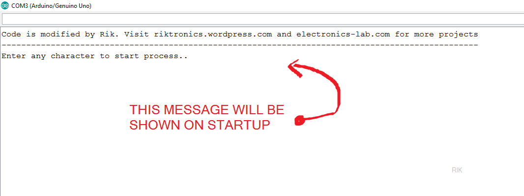
Well, now you need to type a single character like a, b, x etc. and hit Enter↵ to initiate the process. The Arduino code is smart enough to detect your ATtiny model automatically and write correct fuses according to it. You don’t need to specify model or fuse settings. It’ll do all for you. The code can detect 7 different ATtinys. So, after you’ve entered a character you can see the current fuse settings (which bricked the IC) of your ATtiny, and then it will be over-written with correct one, now once again the current fuse setting (which is correct now) is shown. Done.
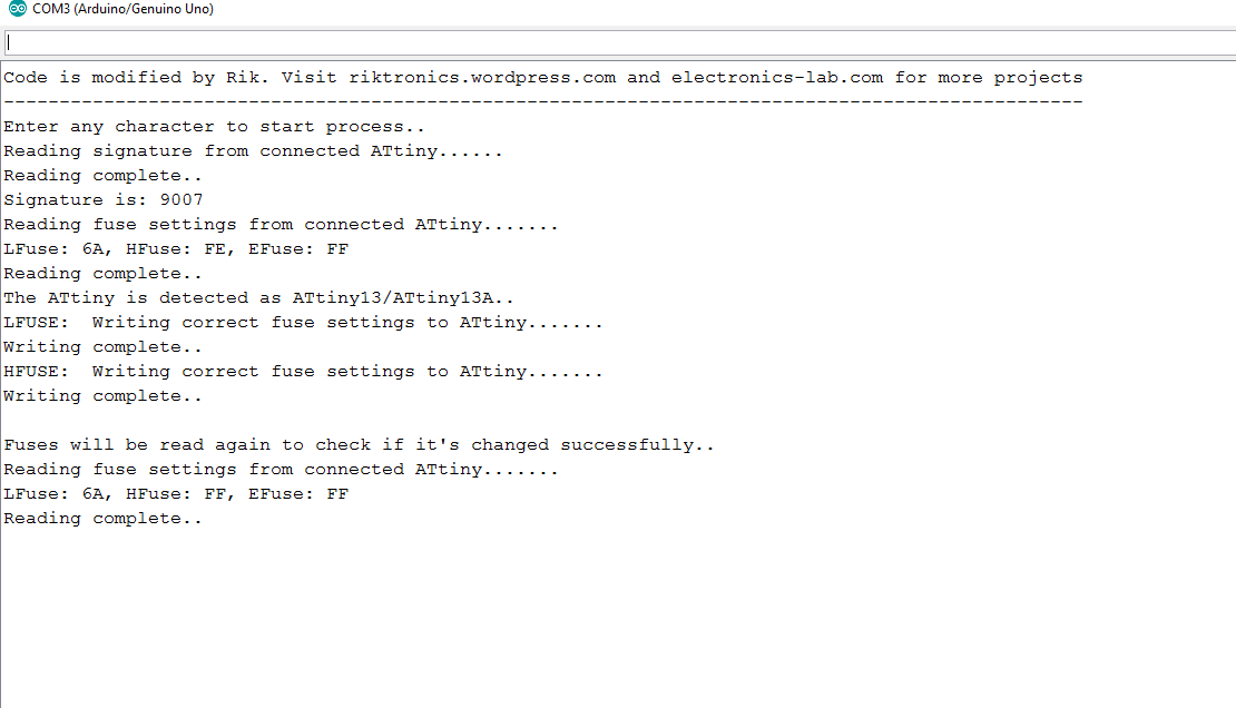
If you look at the image carefully, you can see the initial fuses were LFUSE: 6A HFUSE: FE. That indicate’s, reset was disabled in the ATtiny (as I’ve used it as normal I/O pin because I needed six I/O pins), hence it stopped responding to ISP programmers. The HVP set it to default LFUSE: 6A HFUSE: FF. Now it’s ready to talk to ISP programmer, 🙂
Next, turn off 12V power supply, detach arduino from PC, remove IC from socket and program it using your ISP programmer as you normally do.
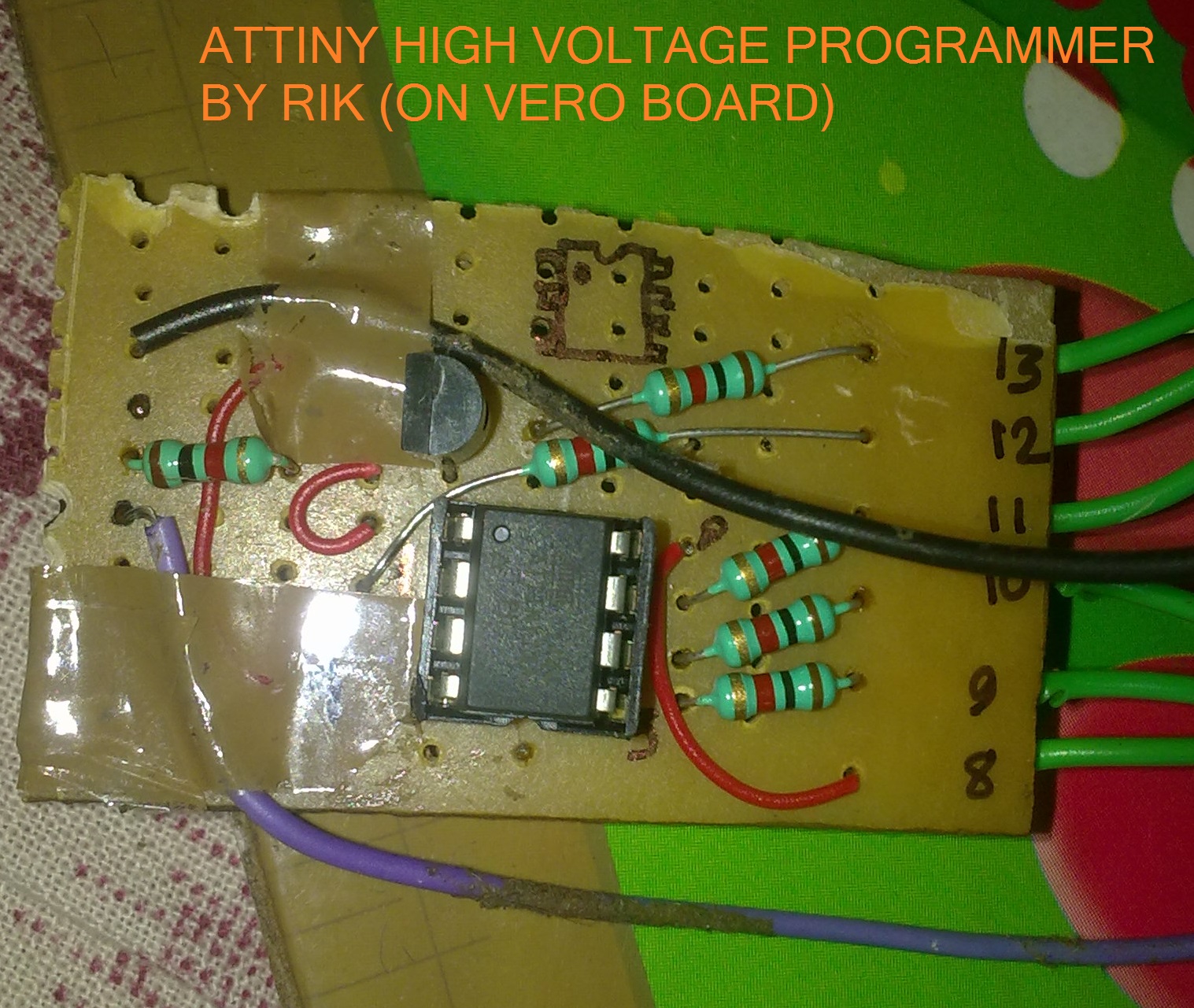
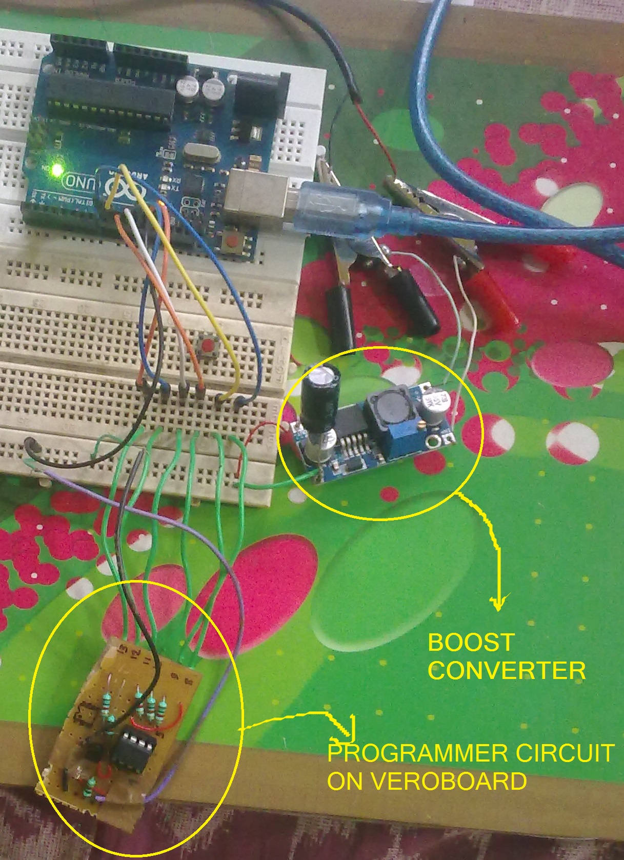
SOME PRACTICAL SNAPS
I made the circuit on veroboard, and I was in damn hurry. So the board is not a piece of art 😉 , but it’s working like a charm. Below are some snaps of the board:
So, that’s how it works. I hope you can recover your bricked ATtiny too. If this article helped you, let me know in comments. And if you have any questions, don’t hesitate to ask. Thank you. 🙂


not working…..
Hi Aman, please let me know what issue you are having. It should work unless your ATtiny is physically damaged. If the MCU is somehow got fried, you can do nothing. Please elaborate the problem you are facing. “Not working” barely explains anything.
It worked. Thanks a lot 🙂
Thanks for letting me know, Kaustav. I’m glad it worked.Please keep visiting electronics-lab.com.
Hi, thanks for this how-to.
I setup circuit and uploaded and ran it. The message says that signature is FFFF and initial fuse is FF, FF and FF. Then the second fuse reading is also FF, FF and FF.
I triple checked setup and wiring and tried it three times. Still same.
It looks like my attiny85 is fried?
Try to do it without the resistors except R4.
I did’t work for me before i did remove resistors between Arduino and ATtiny85
increase dalay microsecond from 20 to 60 !!!!!!
I followed the steps and my ATtiny is working again great aid!!
Worked great at first try on breadboard! Now to do something more permanent. 🙂 Thanks a lot!
Thanks for your feedback, glad it worked!
evening, thanks this is brilliant as keep changing the code to 16mhz and bricking the atting85.issue i’m having is printed of the PCB and writtening is backwards but if i flip the image the reset pin is on the worng side.
is the one with the written backwards the correct one.
Cheers
Thank you so much! It works perfectly! When I brick a chip, the easy way is to throw it away and get another one. But it is so wasteful because it is still working, just the fuse was deranged. I am so happy that I learned a lot during the process as well.
is it necessary to use 12v? can i use 10v instead of 12?
Yes, 12Vdc is recommended by Microchip.
I need this reset pin as an input, so I have to burn the fuses every time I upload a sketch while I develop and test my app to attiny85. Is there a way around or a programmer that can do both without get ruined.
Hi, thank you .
It works flawless, i brick an attiny85 changing to Ext Clock 🙁 , now its alive.
Happy new year!
Thanks for your feedback on this tutorial. Have a Happy New Year 2019!
Hi Rik,
thanks for the wonderful tutorial.
I took your code and build a simple to use Arduino version available at https://github.com/ArminJo/ATtiny-HighVoltageProgrammer_FuseEraser
Thanks for point us to your revision of this HV programmer.
There’s a current limit for the 12v power supply?
Can I use a PC power supply?
Any 12Vdc power supply with at least 500mA capacity will work.
Can you provide an equivalent circuit board diagram for the Attiny 84
It’s the same as the above.
Tie PA0, PA1 and PA2 to Ground (Pins 11, 12 and 13).
Tie PA1, PA1 and PA2 to Ground (Pins 11, 12 and 13).
I setup circuit and uploaded and ran it. The message says that signature is FFFF and initial fuse is FF, FF and FF. Then the second fuse reading is also FF, FF and FF.
I triple checked setup and wiring and tried it three times. Still same.
Hi All,
I am facing the same problem Paolo, has mentioned above.
Setup Details:
> Programmer : Arduino Nano board loaded with AVR High-voltage Serial Fuse Reprogrammer given above..
> uC to be unbricked : ATtiny44A
> PA0, PA1 and PA2 are Grounded.
> 12V bench power supply.
I verified voltage on RESET pin PB3 (Pin4) using DMM. Its correctly changing between 12V and 0V as per the program. So BC548 is working as expected. Below is the output I am getting. any help would be greatly appreciated.
Entering programming Mode
Signature before: FFFF
LFuse: FF, HFuse: FF, EFuse: FF
LFuse: FF, HFuse: FF, EFuse: FF
Signature After: FFFF
Exiting programming Mode
Hi Gururaj
Is the ATtiny44A fitted to a board? Is there any other circuitry connected, particularly to the RESET pin?
I found this
https://www.instructables.com/id/AVR-Attiny-fusebit-doctor-HVSP/
that you could use to confirm the High Voltage Serial Programmer connections to the ATtiny44.
Best of luck
Mike
Hi Mike,
Thanks for the reply.
Though the ATTiny44A is soldered on the PCB, nothing else is connected to any of the pins (See images below).
I have just taken out ATTiny44A’s pin to a SIL header which I connect to the Arduino NANO’s Pins.
I even tried soldering wires directly to 44A’s pins (Without any board/socket as in Image 4 below) and connected them to Arduino pins. No luck, Got the same result.
I have uploaded the images of my circuit and board here.
1) Circuit Diagram, Board and Connections : https://ibb.co/M2Pr5NS
2) Arduino Connections : https://ibb.co/3yX0hv4
3) Bread board closeup : https://ibb.co/0ynTk4R
4) Bare IC connections : https://ibb.co/0J3JSS6 (Note in this image I have not connected purple wire CLKI which was connected to PCB at the time I took the Pic.)
Thanks in Advance.
Regards,
Guru
Hi Gururaj
My eyes are not what they once were, so I cannot quite make out the detail as I would like.
In the photograph of the ’44 on its own, i don’t think PA0, PA1 and PA2 (pins 11, 12 & 13) are connected to Ground.
I cannot see a supply to the Arduino Nano itself, in the photograph showing this.
By the way, what is this supply? I am not familiar with the Nano.
Take care
Mike
Hi Mike,
Sorry for the low resolution image. Pictures were taken at the night.
1) Pin 11, 12, 13 are connected to Pin 14 which is the Ground pin. In the image shown here (https://ibb.co/kGczdkW) Top right 4 pins are 14, 13, 12 and 11.
Just to make it clear, these pins (11, 12 and 13) are opposite to CLKI (pin-2) to which “Purple” colored wire is connected.
2) Supply to Arduino Nano is from a laptop’s USB port through serial cable.
3) Supply voltage to Nano is 5V from USB port. It has a 3.3V output also which I am using to power up ATTiny44.
I am open to feedback(s). Please feel free to correct me if I have done anything wrong in the circuit.
Regards,
Guru
Updated the image. Please use this link
1) Circuit Diagram, Board and Connections : https://ibb.co/kGczdkW
Hi Guru
‘3) Supply voltage to Nano is 5V from USB port. It has a 3.3V output also which I am using to power up ATTiny44.’
To enter and control the AVR High Voltage Serial Programming the supply to the target and the +12V to RESET must be controlled with fairly critical timing. The Arduino HV Serial Fuse Programming sketch controls both the +12V to RESET and the supply to the target to achieve this timing.
In your circuit, is the supply to the target permanently on, or is it controlled via a Nano GPIO?
Take care
Mike
Hi Mike,
In my circuit Both 12V and Supply voltage to pin 1 of ATtiny44 is controlled by Nano. D8 pin of Nano is supplying power to Attiny44. 12V to reset pin of Attiny is controlled by D13 pin of Nano through BC548 transistor.
Sorry for the earlier message in which I have written I am using 3.3V from Nano. Please ignore it. D8 pin of nano is used..
At last I have come to conclusion that ATTiny44’s (50 Nos) I got it from Aliexpress are Fake ones. so trying to buy few of them from local market or some genuine seller. I’ll keep you posted on my findings.
Thanks again for replying.
Regards,
Guru
Thanks for that solution. In my case, I had to add a “chipErase” routine in order to reprogram the whole chip and unlock it. Do you believe people sold me locked chips? Grrrrrr! 🙂
Sorry, I forgot to put a link to modified code, for erasing the chip: https://penso.eu.nom.br/Tecnico/UnbrickTiny85
Has anyone a scheme for attiny84. This article is not so clear and things changed three times down the comments
It’s the same as the one published. We always try to keep our articles up to date. If you think something needs to be changed/improved, just drop a comment.
It is working when I shorted the R5.
One more thing, I used both Uno and Nano to recover the RESET pin without an issue. Thanks for the post!
yess its work 100% thanks
hi, what modifications I must do to use it to recover a bricked atmega88pa ?
Hello,
Not an expert in electronics but i am trying to fix one tiny45 that is on the relay board.
Is it possible that the fuses are causing the “signature” issues which prevent the PC to recognize the device. Also is it possible to perform this unbricking while tiny is soldered on the board. And third, ig i manage to unhrick it will this erase the sw that was on the chip for controling the relays. Thank you.
Hi i was bricked attiny2313, what will be fuse signature?
Hi Rik,
That worked first time for me! I was experimenting with clock speeds and had the tiny85 down to 14.7kHz but found my Pololu programmer wouldn’t program it then (not sure what lowest workable speed is). I didn’t bother with 4 of the resistors and took care to wire them up right. Only used the resistor on the 12v supply and the transistor base resistor. Actually, I made an adaptor for AVR programming (takes t85, t84 or mega328) that has 6 pin ISP socket for the Pololu programmer. Adaptor also has pins so AVRs can be run in the adaptor with an adjacent breadboard for other peripherals. I added the transistor and 2xresistors to it so it can be wired up in situ to un-brick it. Many thanks for the simple design. Joe
The sketch blocks at readSignature when I try and run it. Any ideas what causes it?
thank you. It worked nice.
Hey, please tell me about connection to use a Arduino mega 2560. I am a newbee and bricked the tiny13a with wrong clock. Thanks a lot