


A window detector circuit, also called window comparator circuit or dual edge limit detector circuit is used to determine whether an unknown input is between two precise reference threshold voltages. It employs two comparators to detect over-voltage or under-voltage condition.
This circuit utilizes two comparators in parallel to determine if a signal is between two reference voltages. If the signal is within the window, the output is low thus RELAY is in off condition and also LED is off. Relay provides normally ON and normally OFF switch. If the signal level is outside of the window, the output is high and Relay is in ON condition. For this design, the reference voltages are generated with help of two Trimmer potentiometer. One pot used to set the high voltage level and another one to set the low level voltage adjust. LM358 op-amp used as comparator, it circuit works with 12V DC supply and consumes 50mA current when Relay is in ON state.
Window Comparator – Window Detector with relay output – [Link]
RELATED POSTS
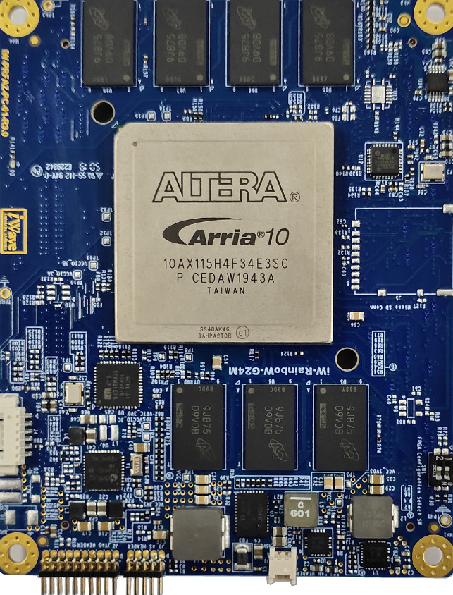 24 September, 2020 iWave Launches Industry Latest High-End FPGA SOM Based on Arria 10 GX FPGA
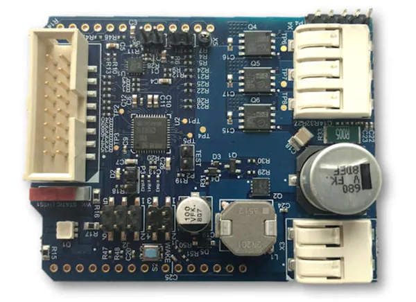 31 January, 2022 Infineon Technologies MOTIX™ BLDC TLE956X Motor Control Shield
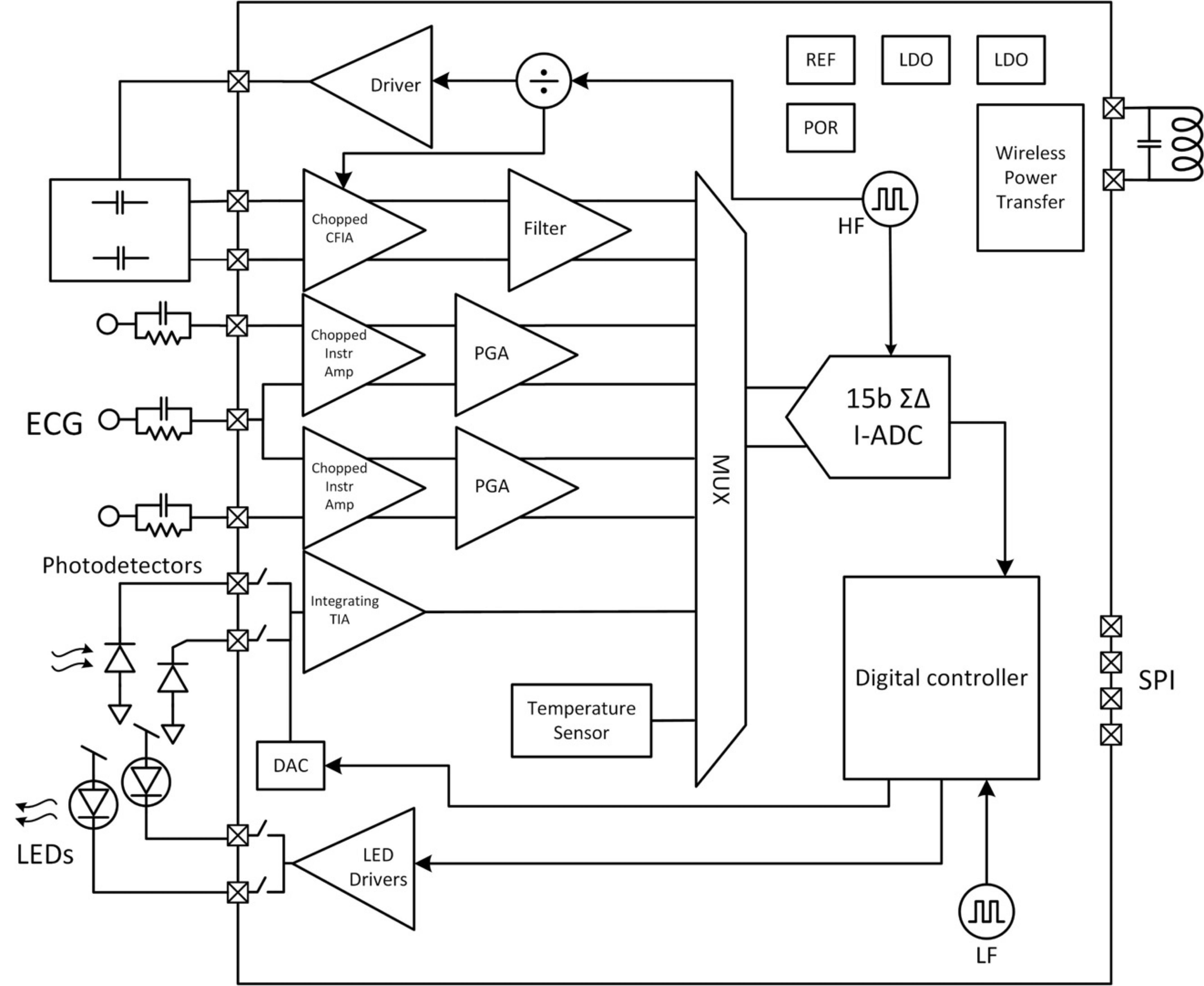 17 February, 2022 EnSilica ENS62020 ultra-low power vital signs sensor interface IC for wearable healthcare and medical device markets
 20 March, 2024 u-blox launches new GNSS platform for enhanced positioning accuracy in urban environments
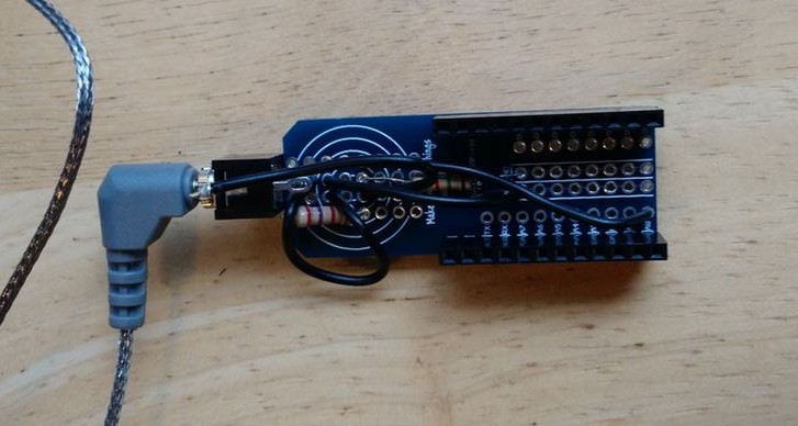 22 October, 2015 Bluz Grill Thermometer
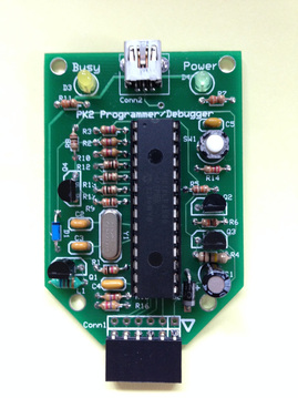 1 November, 2015 Build Your Own PICKit 2 Programmer


