Join the Community
Main Menu
Efinix Ti125 FPGA Targets Compact, Power-Sensitive Edge AI
Dragon Q8B Packs Edge AI, Dual 2.5GbE, and Triple 4K Output
Alinx HEA13 FPGA Development Board Supports Jetson Thor
PEAK Enters Automotive Ethernet with New Media Converter
Mastering the Curve: Layout Strategies for FPC Bend Radius and Reliability
From Hearing to Understanding: MEMS Microphones as a Foundation of Robotic Perception
How to Clean a Soldering Iron Tip Without Ruining It
Why PVC Remains a Go-To Material for Electronics Enclosures and Equipment Mounts
Analog To Digital Conversion - Sampling and Quantization
Positive Feedback in Electronic Circuits
Temperature Sensors
Magnetostatic Fields In Material Bodies
3-Wire Electret Microphone Pre-Amplifier
12W Step Up DC-DC Converter using MAX1771
Sound to Light Color Shield for OLEDUINO v2
Multipurpose Motor Driver Shield for OLEDUINO v2
An Introduction to RF Theory, Practices, and Components: The Ins and Outs of RF
The Growing Decentralization of Power Grids
The Ti125 packs 123K logic elements, sub-milliwatt static power, 2.5 Gbps MIPI I/O, and hardware SEU correction into a footprint...
Powered by Snapdragon 8cx Gen 3, the Dragon Q8B combines dual 2.5GbE, PCIe expansion, Wi-Fi 7 support, and up to 32GB RAM for...
Powered by an AMD Virtex UltraScale+ FPGA, the HEA13 FPGA development board supports NVIDIA Jetson AGX Orin and Jetson Thor...
HMS Networks' PEAK brand debuts its first Automotive Ethernet device, bridging 100/1000BASE-T1 with standard Ethernet for vehicle development and...
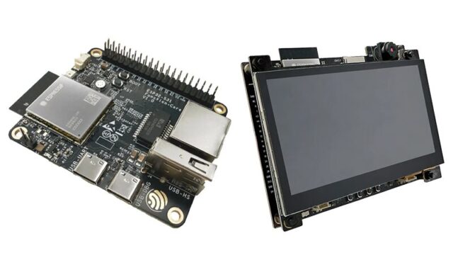
Built around ESP32-P4 and ESP32-C61 SoCs, this AIoT development board supports Wi-Fi 6, Bluetooth 5, MIPI camera/display...
Matter-enabled DIN rail smart switch with energy monitoring, overload protection, and support for high-power loads up to 7,680W.
A new IEEE 802.15.4ab-compliant 22nm CMOS implementation uses narrowband assistance to improve indoor localization performance...
Two new high-performance RISC-V devki/devboard have arrived, bringing Gigabit Ethernet, Wi-Fi 6, and advanced multimedia interfaces to smart home...
The SPDT device combines 0.5 dB insertion loss, 95 dBm IIP3, and cryogenic operation for next-generation test, satellite, and...
Youyeetoo R1 v3.0 upgrades its Rockchip RK3588S SBC with four USB-A ports, up to 32GB RAM, 6 TOPS AI, NFC support, and M.2...
A compact Wi-Fi-enabled debugger whcih combining SPI, I²C, UART, CAN, GPIO, ADC, and DAC into one browser-accessible platform — no...
The SDG8000A pairs 16-bit resolution and 12 GSa/s sampling with direct 5 GHz output and vector signal creation for wireless,...