Build Your Own Scalar Network Analyzer to Test Frequency Response of Filters and Networks
Radio Frequency Network Analyzers is one important tool required for testing the frequency response of filters and networks, but as we all know, buying a regular RF test equipment can be quite the expenditure. This was why hobbyist Stephen Merrifield, who after seeing the increased need for more RF testing capabilities as a result of increased awareness of wireless applications, decided to build his own simple scalar network analyzer with just a few components.
Radio Frequency Network Analyzers is one important tool required for testing the frequency response of filters and networks, but as we all know, buying a regular RF test equipment can be quite the expenditure. This was why hobbyist Stephen Merrifield, who after seeing the increased need for more RF testing capabilities as a result of increased awareness of wireless applications, decided to build his own simple scalar network analyzer with just a few components.
As the name implies, a scalar network analyzer is a type of an RF network analyzer that measures only the amplitude properties of a device over a range of frequencies. It does so by outputting a sine wave sweeping over a particular bandwidth and then measuring the amplitude of every increased frequency. So when any device is connected to the scalar network analyzer, the device’s frequency response over that bandwidth is reflected by the amplitude of the sine wave at each frequency after passing through the device.
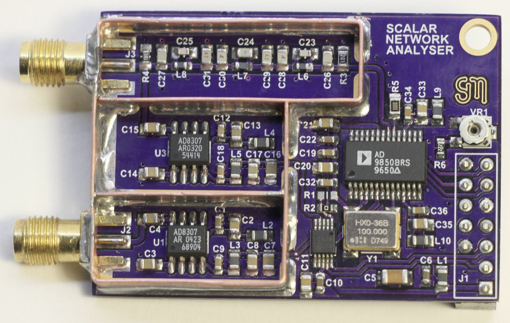
Merrifield was able to achieve this with his design using just a combination of an AD9850 DDS chip, a multi-channel ADC, AD8307 logarithmic amplifier chip, Raspberry Pi, and general I/O interface. The DDS chip outputs the sweeping sine wave and sends it to the AD8307 log amplifier that conditions the input signal into the SNA before passing it on to the ADC for digitizing. The output of the DDS is again conditioned by another AD8307 after which it is sent as output to a second channel of the ADC to compensate for variations on the DDS’s output that could arise as a result of loads of devices being tested. The digital output from the ADC is sent via an I2C to a GPIO header.
Speaking about the flexibility of the design, Stephen mentioned that the:
“pinout matches a Raspberry Pi, but any micro-controller may be used to program the DDS and read the ADC. The analog bandwidth has been deliberately set at 30MHz. There is approximately 0.02dB variance between 1kHz and 30MHz. The noise floor averages around -69dB with shielding fitted.”
The project is entirely open-source and the firmware for the Raspberry Pi was written in C to allow for easy porting across different platforms.
Stephens Hackaday Project Log can be found here. It contains the schematic and every other resource you might need to build your own version of the scalar network analyzer.


