SmartPhone Controlled Home Automation using Raspberry Pi and BleuIO
Home automation involves automating household environment equipment. To achieve that, we have created a smart bulb that can be controlled remotely using a smartphone app.
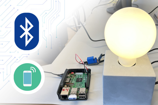
Home automation involves automating household environment equipment. To achieve that, we have created a smart bulb that can be controlled remotely using a smartphone app. The aim of this project is to control different home appliances using smartphones at your home.
Introduction
This example is showing how to control a GPIO pin on a RaspberryPi remotely from a smartphone (or another BleuIO Dongle).
For this example we will need:
- A RaspberryPi
- A BleuIO Dongle (https://www.bleuio.com)
- Our example python script (https://github.com/smart-sensor-devices-ab/bleuio_rpi_switch_example)
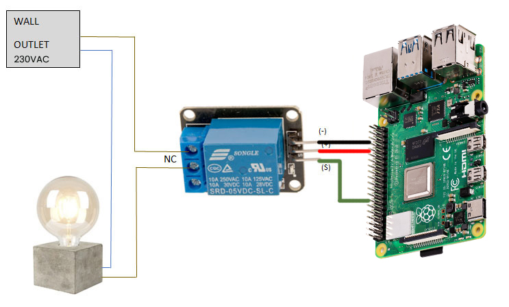
- A way to connect to the GPIO Pin (Like a 5V Relay and a Lightbulb)
Beware:

Always be very careful when experimenting with AC, electrical shock can result in serious injuries! NOTICE OF RISK; DISCLAIMER OF LIABILITY
WARNING – THIS PROJECT INVOLVES HIGH VOLTAGES THAT CAN CAUSE SERIOUS INJURY OR DEATH. PLEASE TAKE ALL NECESSARY PRECAUTIONS, AND TURN OFF ALL POWER TO A CIRCUIT BEFORE WORKING ON IT.
Connecting the relay
Always be very careful when experimenting with AC, electrical shock can result in serious injuries! NOTICE OF RISK; DISCLAIMER OF LIABILITY
Instructions for bleuio_rpi_switch_example.py
- Connect the BleuIO Dongle to your RaspberryPi.
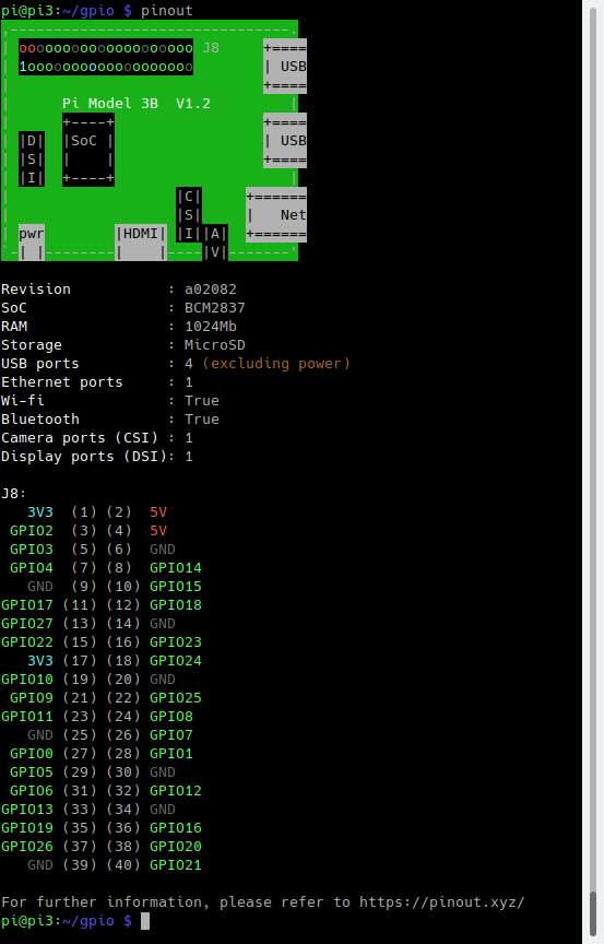
- Edit the variable ‘switch’ in the script to the GPIO pin you want to use. (You can use the command pinout to get a graphical view showing you the GPIO pins for the board)
- Finally, just run the python script and use your phone to connect to the BleuIO Dongle and send on/off messages to control the GPIO!
Instructions for connecting to the BleuIO to mobile
- Download a BLE scanning App that can connect and read/write to a device. (Like nRFConnect or BLEScanner) Android, IOS
- Look for the dongle, it will be advertising as ‘BleuIO’.
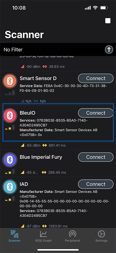
- Connect to the BleuIO Dongle.
- To enable BleuIO to recieve commands you must first write 0x01 to the Flow Control characteristic (UUID: 0783b03e-8535-b5a0-7140-a304d2495cb9)
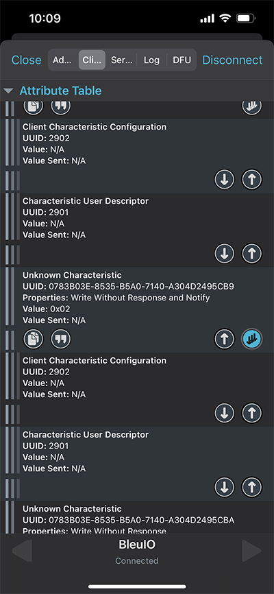
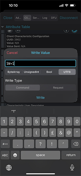
- Now you can write to the Server RX Data characteristic (UUID: 0783b03e-8535-b5a0-7140-a304d2495cba) to control the GPIO.“SW=1” for ON
“SW=0” for OFF
The script
Here is the python script that receives the messages from the smartphone app and helps control the light.
#!/usr/bin/python3
# Copyright 2022 Smart Sensor Devices in Sweden AB
#
# Permission is hereby granted, free of charge, to any person obtaining a copy of this software and associated documentation files (the "Software"),
# to deal in the Software without restriction, including without limitation the rights to use, copy, modify, merge, publish, distribute, sublicense,
# and/or sell copies of the Software, and to permit persons to whom the Software is furnished to do so, subject to the following conditions:
# The above copyright notice and this permission notice shall be included in all copies or substantial portions of the Software.
#
# THE SOFTWARE IS PROVIDED "AS IS", WITHOUT WARRANTY OF ANY KIND, EXPRESS OR IMPLIED, INCLUDING BUT NOT LIMITED TO THE WARRANTIES OF MERCHANTABILITY,
# FITNESS FOR A PARTICULAR PURPOSE AND NONINFRINGEMENT. IN NO EVENT SHALL THE AUTHORS OR COPYRIGHT HOLDERS BE LIABLE FOR ANY CLAIM, DAMAGES OR OTHER LIABILITY,
# WHETHER IN AN ACTION OF CONTRACT, TORT OR OTHERWISE, ARISING FROM, OUT OF OR IN CONNECTION WITH THE SOFTWARE OR THE USE OR OTHER DEALINGS IN THE SOFTWARE.

import time
import serial.tools.list_ports
import serial
import RPi.GPIO as io


switch = 7  # Edit this to suit your setup! (7 = GPIO 04), use command pinout to graphically show you the GPIO pins for the board
io.setmode(io.BOARD)
io.setup(switch, io.OUT)

master_array = []
index = 1
dongle_port = ""

print("\nWelcome to BleuIO RaspberryPi Switch Example!\n")

print("\nPlease insert dongle...")
try:
    while len(master_array) == 0:
        m_ports = serial.tools.list_ports.comports(include_links=False)
        for port in m_ports:
            if str(port.hwid).__contains__("VID:PID=2DCF"):
                master = port.device + " " + port.hwid
                if master.__contains__("VID:PID=2DCF:6002"):
                    print("Found dongle in port: %s" % port.device)
                    master_array.append(master)
                    dongle_port = port
                    break

    for dongle in master_array:
        print("\nConnecting to BleuIO @ %s\n" % dongle)

    time.sleep(0.5)
    dongle_conn = serial.Serial(
        dongle_port.device,
        115200,
        timeout=1,
    )

    if not dongle_conn.is_open:
        dongle_conn.open()

    print("Starting Advertising...")
    dongle_conn.write("AT+GAPDISCONNECTALL\rAT+DUAL\rAT+ADVSTART\rATI\r".encode())
    read_tries = 0
    dongle_resp = ""
    while read_tries < 20:
        dongle_resp = dongle_conn.readline().decode()
        if "Not Advertising" in dongle_resp:
            dongle_conn.write("AT+ADVSTART\r")
        if b"Advertising\r\n" in dongle_resp.encode():
            break
        read_tries += 1
        time.sleep(0.01)

    if dongle_resp:
        print("BleuIO is %s" % dongle_resp)
    else:
        print("ERROR! No response...")
        exit()

    print(
        "Going into loop, waiting for signal to turn switch on/off...\n(Press Ctrl+C to abort)"
    )
    while True:
        try:
            dongle_resp = dongle_conn.readline().decode()
            if "SW=0" in dongle_resp:
                print("Turn Switch off!")
                io.output(switch, io.LOW)
            if "SW=1" in dongle_resp:
                print("Turn Switch on!")
                io.output(switch, io.HIGH)
        except KeyboardInterrupt:
            if dongle_conn.is_open:
                dongle_conn.write("AT+GAPDISCONNECTALL\rAT+ADVSTOP\r".encode())
                dongle_conn.close()
                io.cleanup()
            print("\nBye!")
            exit()

except Exception as e:
    print("(ERROR: %s)" % (e))
Output
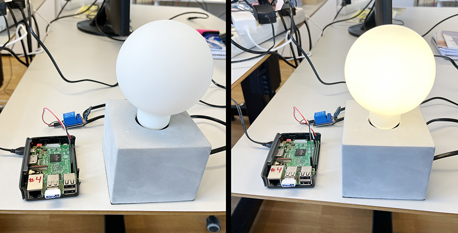
We have tested the script using nRFConnect app from both IOS and Android phones to turn on/off the light bulb. Here is the output of this project.


