


Wireless Tag WT99P4C5-S1 dev board combines ESP32-P4 RISC-V SoC with ESP32-C5 dual-band WiFi 6, Zigbee, and Bluetooth module
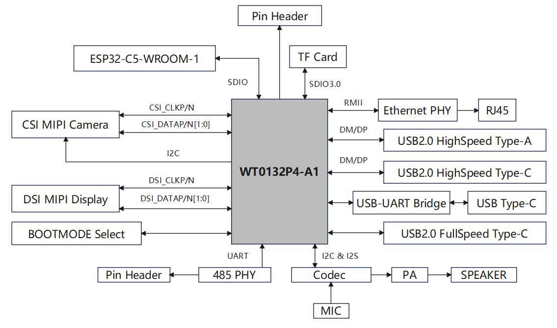
The Wireless Tag WT99P4C5-S1 is a dev board that combines the ESP32-P4 RISC-V SoC with an ESP32-C5 module for dual-band Wi-Fi 6, Bluetooth LE 5.0, and 802.15.4 (Zigbee, Thread, Matter) wireless connectivity.
Designed for IoT, gateway, and embedded applications, it supports MIPI DSI and CSI interfaces for display and camera, has Fast Ethernet, a microSD slot, audio codec (ES8311), RS485 via SIT3088EESA, and multiple USB ports. The ESP32-P4 includes a dual-core RISC-V CPU up to 400 MHz, an AI instruction set, and a VPU with H.264 and JPEG support. Expansion is possible via GPIO headers for both the P4 and C5 chips.
WT99P4C5-S1 dev board specifications
- Core module: Wireless Tag WT0132P4-A1 with Espressif ESP32-P4 SoC
- Dual-core 32-bit RISC-V HP CPU @ up to 400 MHz, with AI instructions and FPU
- Single-core 32-bit RISC-V LP MCU @ up to 40 MHz
- 768 KB HP L2MEM, 32 KB LP SRAM, 8 KB LP TCM RAM
- 128 KB HP ROM, 16 KB LP ROM
- 16MB or 32MB PSRAM
- 2D Pixel Processing Accelerator (PPA), H.264/JPEG VPU
- 16MB NOR flash
- Optional wireless module: ESP32-C5-WROOM-1
- Dual-band WiFi 6 (802.11ax), Bluetooth LE 5.0
- IEEE 802.15.4 for Zigbee 3.0, Thread, Matter
- Storage: MicroSD card slot
- Display interface:
- MIPI DSI connector
- LCD TP connector for touchscreen
- Camera interface: MIPI CSI connector
- Audio:
- ES8311 audio codec
- Built-in microphone
- Speaker connector
- Audio amplifier chip
- Networking:
- 10/100 Mbps Ethernet port (RJ45)
- Optional WiFi 6, Zigbee, Thread via ESP32-C5
- USB:
- 2x USB Type-C ports
- 1x USB Type-A port
- USB-to-UART for debugging
- Serial: 2-pin RS485 terminal block (SIT3088EESA chip)
- Expansion:
- 28-pin GPIO header (ESP32-P4)
- 2x 8-pin GPIO headers (ESP32-C5)
- Buttons & LEDs: Power switch, BOOT & EN buttons, power LED
- Power supply:
- 5V input via USB-C
- Onboard 5V to 3.3V LDO regulator
- Dimensions: 25 x 20 mm (core module), board size TBD
At the time of writing, documentation for this ESP32-P4 dev board is limited, but there is an 11-page English datasheet for the ESP32-P4 module and a 13-page datasheet in Chinese for the board itself, both available on the product page. Software support uses ESP-IDF, the official development framework for ESP32 chips. Although there is a GitHub link with code samples, it seems to be private or not yet available. Currently, there are no detailed tutorials, so users should be comfortable using ESP-IDF and can check existing resources for ESP32-C5 and ESP32-P4 to get started.
Previously, we have written about the ESP32-P4-NANO development board and the ESP32-P4-Module development board, both are ESP32-P4-based development boards designed for various applications. Feel free to check those out if you are interested in the topic.
The Wireless Tag WT99P4C5-S1 board sells on AliExpress for about $25 with an ESP32-C5 module. The WT0132P4-A1 ESP32-P4 module isn’t on AliExpress but is available from the company’s store for $5 plus shipping.
RELATED POSTS
 23 July, 2021 Precision Thermocouple Amplifier (Thermocouple to Digital Converter with Linearization – SPI Interface)
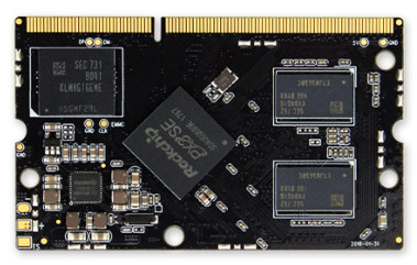 16 June, 2018 Firefly’s Latest Core-PX3-SEJ COM Runs Ubuntu or Android
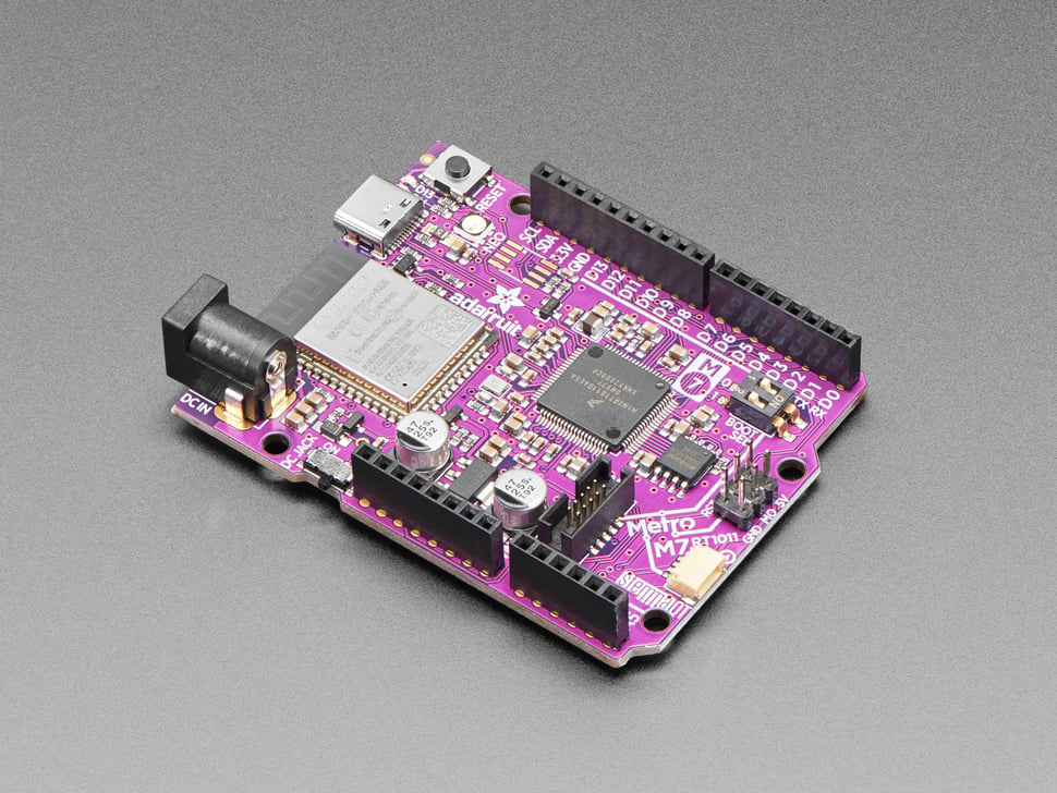 1 June, 2023 Adafruit Metro M7– An Arduino Uno layout board with wireless connectivity
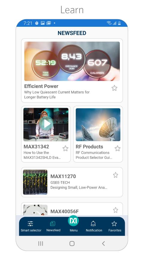 28 August, 2020 Maxim Integrated launches smartphone app for fast Access to its essential analog IC resources
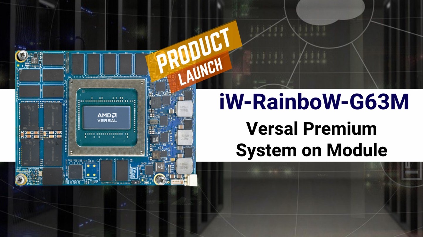 30 May, 2024 iWave Launches iW-RainboW-G63M: AMD Versal Premium System on Module Tailored for Network and Cloud Acceleration
 23 February, 2023 Sierra Wireless Announces New 5G LPWA HL7900 Module Integrating Sony’s Altair ALT1350 Chipset