


Operational amplifiers (OPAMPs) are high performance differential amplifiers in integrated form that can be used in many different ways. A typical OPAMP has a non-inverting input, an inverting input, two dc power pins, one output pin and a few other fine-tuning pins. On the following image you can see a typical diagram of an operational amplifier.
The basic OPAMP operation is simple. If the voltage applied to the inverting input is greater than the voltage applied to the non-inverting input then the output saturates to the negative supply voltage. In addition, if the voltage applied to the non-inverting input is greater than the voltage applied to the inverting input, then the output saturates at positive supply voltage.
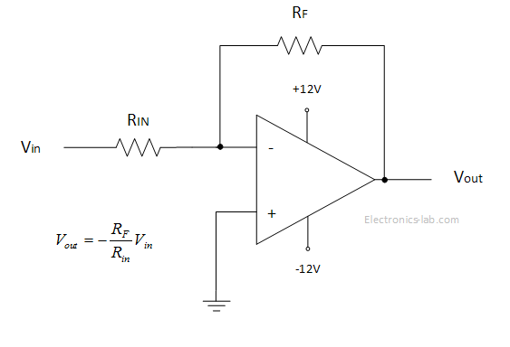
This operation mode is limited and doesn’t give us the full idea behind OPAMP operation. The trick to make an OPAMP more useful is to provide negative feedback from the output to the inverting input. In the image below we see an OPAMP with negative feedback working as an inverting amplifier.
In this configuration a part of the output voltage is fed back to the inverting input and thus the gain of the OPAMP can be controlled and output isn’t saturating. The gain of such an amplifier is controlled by the two resistors Rf and Rin. The minus means that the output is inverted relative to input.
By adding more components on the feedback loop, different OPAMP circuits can be made, such voltage regulator circuits, current to voltage converters, oscillators, filters etc.
Beside the negative feedback, a positive feedback can be used. This way the OPAMP is driven toward saturation and works in either +Vs or –Vs output range. Applications of positive feedback is on comparator circuits and oscillators.
Theory
The basic formula that gives the output voltage in respect to input voltages is as follows. This formula tells that the output voltage is a function of the input voltages difference and of the open-loop voltage gain A0.![]()
This expression is for the ideal OPAMP and can get more complex for the real OPAMPs. Some rules apply to better understand the ideal and real OPAMPs.
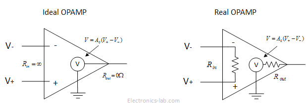
- Rule 1: For the ideal OPAMP the open-loop voltage gain is infinite but for real OPAMP is in the range of to .
- Rule 2: For the ideal OPAMP the input impedance is infinite but for real OPAMPs is in the range to Ω. The output impedance of an ideal OPAMP is zero but for a real OPAMP is in the range 10 to 1000 Ω.
- Rule 3: The input terminals of an ideal OPAMP doesn’t draw any current and typically the same happens for the real OPAMP as the input current is very small.
- Rule 4: This rule applies to OPAMPS having negative feedback and tells us that when a voltage difference exists on the inverting and non-inverting input, the output increases in that direction so that the voltage fed back will keep that difference to zero.
Applications – Negative Feedback
Unity Gain Amplifier – Buffer
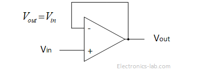
In this configuration the output is connected to the inverting input and according to rule 4 the output will try to keep the difference in the non-inverting input and the inverting input to zero. In this was the output will always be equal to Vin. So the gain of this amplifier is 1. This is useful as long as the input impedance of OPAMP is high and output impedance is low thus acting as a buffer between the input and output. In practical circuit a resistor may be used in the feedback loop to minimize the offset errors due to input bias currents.
Inverting Amplifier
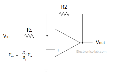
This is a typical inverting amplifier configuration. As we have negative feedback the output will try to keep the voltage in the two inputs equal. As the voltage in non-inverting input is zero the voltage on the inverting input will also be zero. By solving the Kirchhoff’s laws on the junction we get that the gain on this amplifier is:
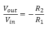
The negative sign tells that the output is inverted according to the input.
Non-Inverting Amplifier
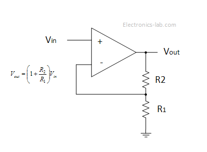
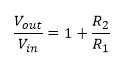
In this configuration the OPAMP works like a non-inverting amplifier. The output voltage will be as high to keep the difference in input voltages to zero. This drives us with a formula for the gain of this amplifier that is:
Note that the output voltage is in phase with the input voltage.
Summing Amplifier
In this configuration the output voltage is equal to the sum of a part of the input voltages. Since the non-inverting input is grounded the voltage to inverting input will also be zero and thus solving for the nodes currents and applying the Kirchhoff’s law we come up with an expression for the output voltage that is as follows:
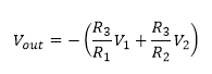
If all resistors are equal then the formula becomes:
![]()
That means the output is equal to the sum of the input voltages but it’s also inverted. To get a positive sum of the input voltages we need to add another inverting amplifier after the summing amplifier.
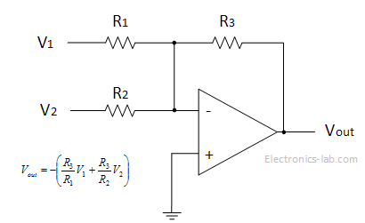
Difference Amplifier
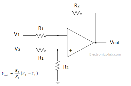
In this configuration the output voltage is equal to the difference of the input voltages. Assuming that no current enters the inputs we determinate the voltage at the non inverting input using the voltage divider equation. Next we apply the Kirchhoff’s law for the inverting junction and assuming that the voltages at the inputs are the same we come up with an expression for the output.
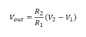
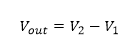
If the resistors are all the same this equation becomes:
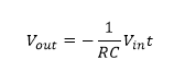
Integrator
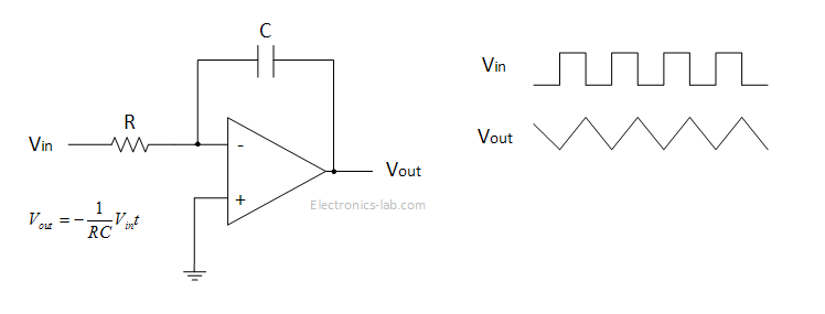
In this configuration the OPAMP circuit is called an integrator, that means that the input signal is integrated at the output. The relation between the output and the input is as follows:
In real world applications a large resistor can be placed in parallel with the capacitor to provide stable biasing. Also a compensation resistor may be needed between the non-inverting input and the ground to correct voltage offset errors.
Differentiator

In this configuration the OPAMP works like a differentiator. The relation between the output and the input is:
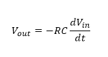
To make this circuit more stable a capacitor may be added across the resistor and a resistor to be added in series with the capacitor, so that high frequency noise is reduced and eliminate the input bias offset voltage.
Applications – Positive Feedback
Positive feedback means that a part of the output signal is feed back to the non-inverting input. This will drive the opamp to the direction of saturation and thus output will be either to positive supply voltage or to negative one. Positive feedback can be used to make comparator circuits and by adjusting the feedback resistor we are able to adjust the hysteresis of the comparator. The term hysteresis means that the comparator has to voltage thresholds, one which the output changes to one direction and another threshold with the output changes to the other direction. This way the output is prevented from swinging from positive output voltage to negative voltage too fast and thus making it more immune to input voltage noise. Let’s see a comparator circuit.
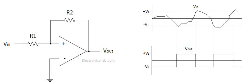
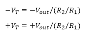
In this circuit let’s assume that output is at positive saturation and input is 0V. In this situation a positive voltage is appearing on the non-inverting input. If the voltage on the input become positive and exceeds the positive voltage threshold the output switched to negative output voltage. Now a negative voltage appears on the non-inverting output and if the output voltage becomes equal or greater than the negative threshold voltage the output switches to positive output voltage. The two threshold voltages are determinate by the following equations:
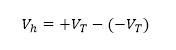
The difference between the two threshold voltages is the hysteresis voltage.
RELATED POSTS
 23 February, 2016 Six boards for rapid IoT development
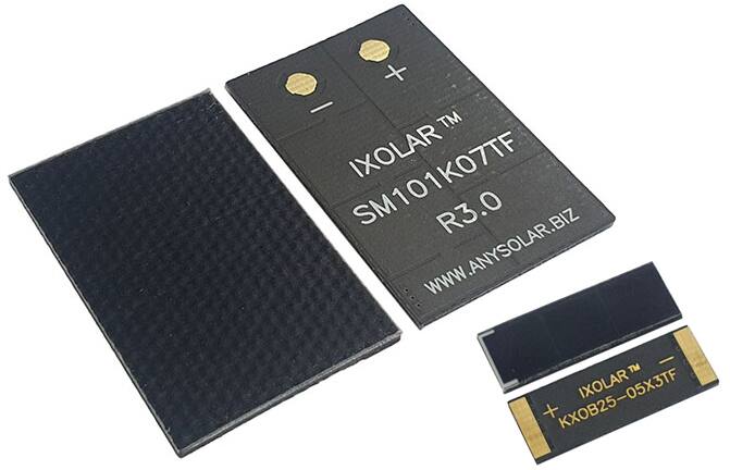 19 March, 2022 IXOLAR™ Thin 1.2 mm, 25% Efficiency Solar Cells
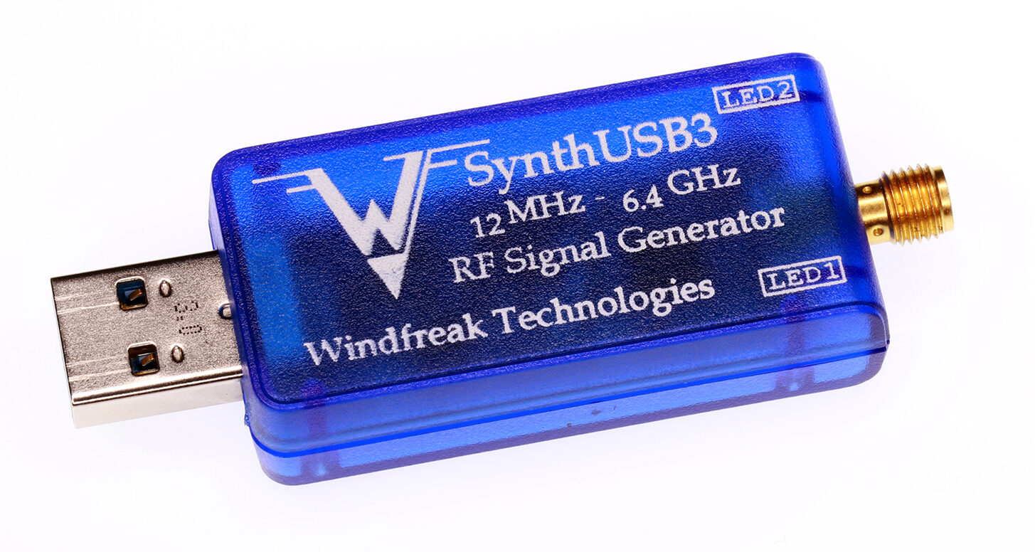 29 January, 2021 Compact SynthUSB3 6.4GHz Microwave Signal Generator
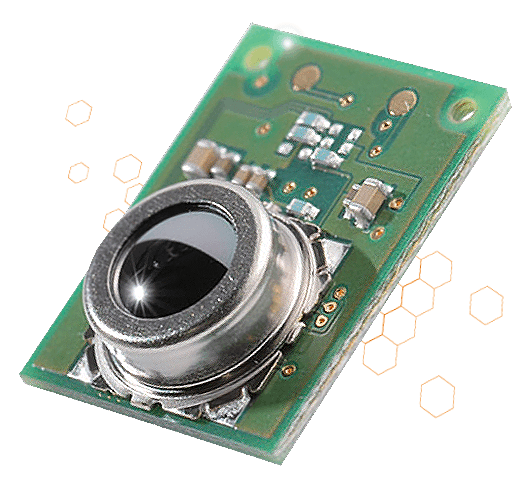 17 January, 2018 Omron’s New Super-Sensitive, Non-Contact MEMS Temp Sensor
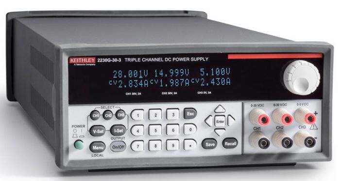 19 December, 2019 Three-channel power supplies deliver up to 375W
 18 November, 2015 HacKeyboard – open hardware mechanical keyboard


