


David Jones made a tutorial on the fundamentals of zener diodes over his EEVblog youtube channel.
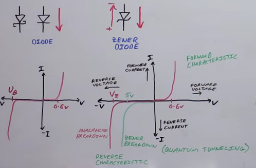
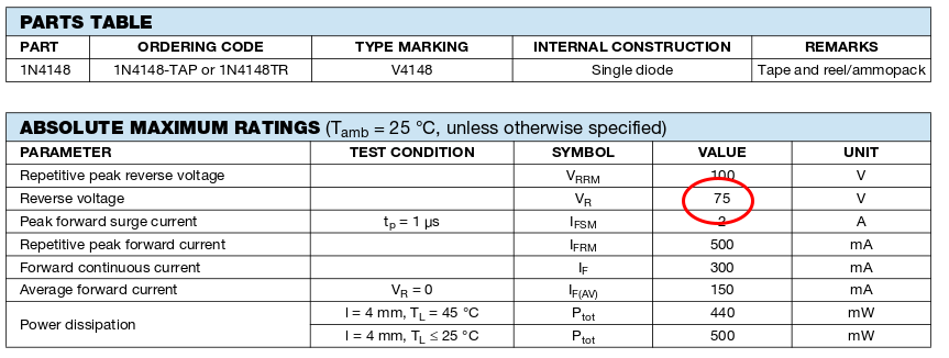
David started the tutorial comparing between zener and regular diode. Both have the same characteristics and same I-V chart, but zener is designed to work in the negative voltage region.”In theory” the regular diode can work in the negative voltage region, but the breakdown voltage, Vb the minimum reverse voltage that makes the diode conduct in reverse, is really high. For example, 1N4148 Vb=75v and this value it is not usable in practical circuits, while Vb in zeners is designed to meet our needs. So diode effectively stops current in negative region until the voltage reaches Vz where it starts to contact current.
David highlighted the difference between Avalanche breakdown and zener breakdown. When you use zener with Vr (aka Vb)<5V then you will have zener breakdown effect and above that you will have Avalanche breakdown effect.
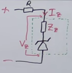
Most important electrical characteristics of zener is Vz (breakdown voltage, aka Vb or Vr), Iz and Zz ( internal impedance of the zener) that you must take them in account when you use a zener in your design.
David demonstrated the main applications of zener:
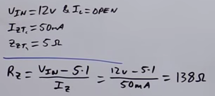
First One: Regulation To 5.1V
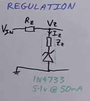
This is because the nature of zener. Zeners have a stable voltage when the reverse voltage reaches the Vz.
David calculated the current limiting resistor Rz value first without attaching the load.
Then he demonstrated in numbers how the regulation output will change when we change Vin from 12V to 15V.
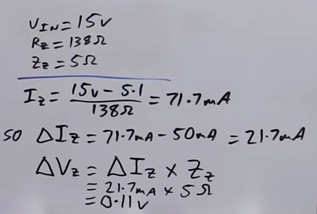
Beside the problem of output voltage variation, we can see that the zener will consume about 70mA to regulate Vin to 5.1V which is a quite considerable amount of current. So using zener for main power regulation in your circuit is not advisable. You can use some well known voltage regulation ICs like LM7805, which have a stable output and a very low quiescent current.
Zener regulation feature still very useful for low power signals.
The high current needed for zener regulation operation will also produce a high power dissipation, P= U*I = 5.1 * 0.05 = 0.255 W which is a considerable power value.
Second One: Clipping/Clamping
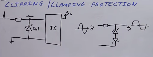
In the end of David’s video tutorial he hocked up a zener with an oscilloscope probe and showed how zener behave in practice.
RELATED POSTS
 5 October, 2020 Microchip Announced New VSC8541RT Gigabit Ethernet PHY RMII / RGMII Transceiver
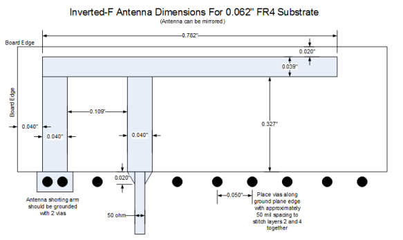 1 December, 2020 Designing with an inverted-F 2.4 GHz PCB antenna
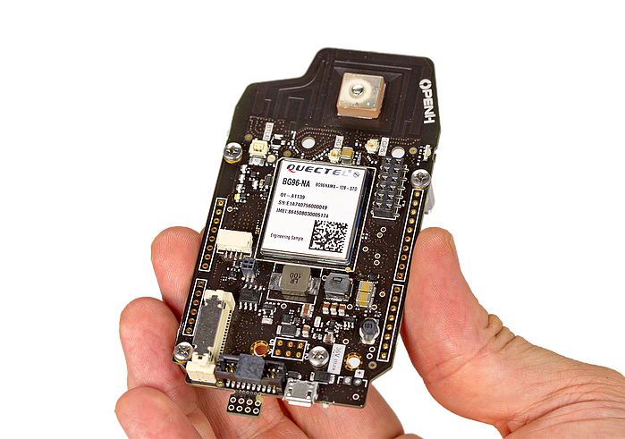 31 May, 2017 Pulsar™ – a 4G cellular board
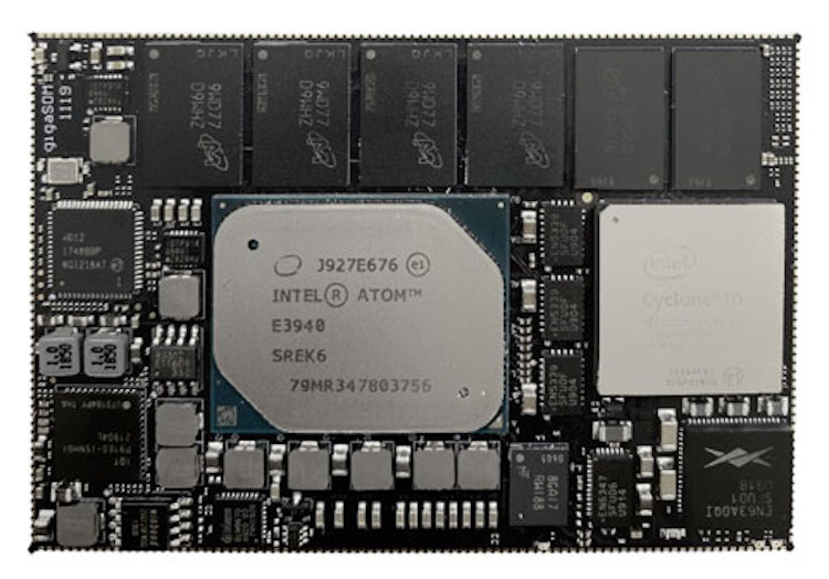 9 June, 2020 Arrow Electronics and Exor launch IoT edge platform for smart factories
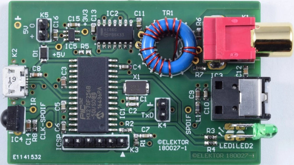 4 April, 2020 Elektor Article: USB-SPDIF Interface
 17 July, 2017 Visual Studio Code Extension for Arduino is now open sourced!


Hi,
A little know fact about zeners is temperature characteristics at different zener voltages. Below 6V it is positive and it is the range were true “Zener” action takes place. Above 6V zener breakdown takes place from avalanche or breakdown. Above 6V this breakdown has a negative temperature characteristic. (And the actual 6V point depends on doping levels.
A funny thing happens at about 6V, the two different modes merge and temp variations is close to zero, really cool. You will find some very good low cost voltage reference diodes at about 6.2V.
Some of these precision zeners reference diodes are really good but they can be expensive. But any old zener at 6.2V is probably going to be “Pretty Good”.
Another area where I see errors is in the use of low voltage zeners at or below the 4.3V point. They have VERY soft knees, watch out.
An area where I often use zeners is protecting the gates of MOSFETs in power switches. The problem is you need a bias resistor and this messes with the nice High Z of the FET gate. But if you check the specs, and watch the temps, you will find higher voltage zeners (like 12V) have VERY low leakages below the knee. This means you can protect a gate and maintain a high Z around the gate circuit.
I have some schematics for battery chargers / DC converters at http://www.sunduino.com and you will see I use a lot of zeners?
Bob K.
thanks for your valuable notes 🙂