Arduino-Based SSD uses an ATmega8 & 8 EEPROM chips
“Now, instead of using an SD card to store configuration files, I can simply send commands via the UART interface to the SSD from an external board and store/retrieve data without the extra code overhead.” SD cards are used for storing information when logging data or retrieving files but with microcontrollers that have shorter RAM or a small number of GPIO pins, storing large amounts of data with an SD card while maintaining a small program can really be tough. There is the issue of extra software overhead and slow access time.
“Now, instead of using an SD card to store configuration files, I can simply send commands via the UART interface to the SSD from an external board and store/retrieve data without the extra code overhead.”
SD cards are used for storing information when logging data or retrieving files but with microcontrollers that have shorter RAM or a small number of GPIO pins, storing large amounts of data with an SD card while maintaining a small program can really be tough. There is the issue of extra software overhead and slow access time.
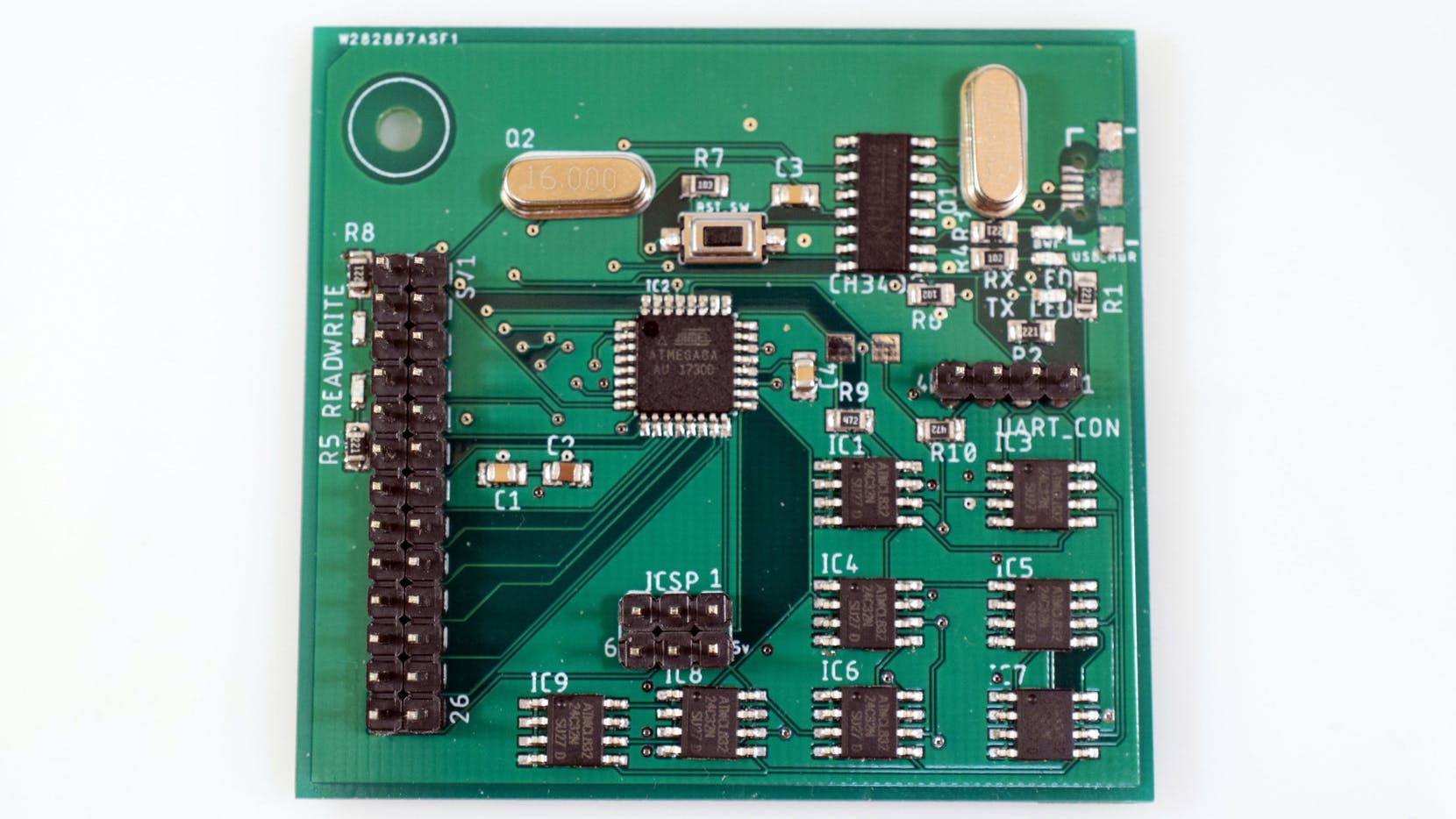
It was in a bid to find a suitable solution to this common problem that “Having11″ came about his new project: the design of an Arduino based SSD that uses an ATmega8 as a controller with several EEPROM chips.
Typically, an SSD is made up of a controller, set of flash chips, and DRAM that acts as a cache. The onboard controller takes in command through an interface, decodes it, and sets it ready to read or write data by the flash that is connected to the controller.
First, he had to decide on the kind of IC to use and the EEPROM seemed to fit perfectly well for the job. The chips, about 256 bytes each, are relatively cheap and easy to interface with. They operate at 5V and eliminate any form of logic level conversion between the EEPROM and the controller.
“As with most projects, it began with a simple sketch on paper. I laid out the rough locations of the components, such as groupi9ng the eight EEPROM chips together and placing the CH340G close to the ATmega8. Then I moved onto creating the schematics.”
He further assembled the board placing each component into their respective location, structured and organized the data, and made a protocol that consists of the host device that can send a command to the SSD for execution and give back a response.
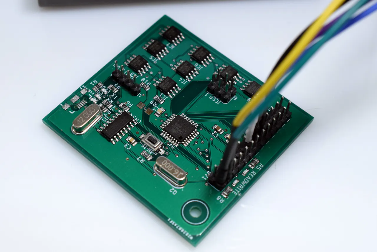
Meanwhile, he added that the board must have been programmed before commands can be sent through the USB or UART; its either you burn the Arduino bootloader into the ATmega8 or use the ICSP header to flash the chip through the SPI interface if you want to conserve space.
“Since I wanted the “SSD” to also communicate over USB, it was necessary to add a CH340G USB t UART converter. To test it out, I connected an FDTI USB to UART converter to my PC and the SSD. Then I wrote a simple python script that can send various commands and print out the corresponding data”.
Now, he has an SSD functioning conveniently as an SD card without extra software overhead.
More information about the project including a step-by-step guide to building the project can be found here


