DIY Arduino Nano HV UPDI Programmer
In May, Arduino released a guide on how you can create a UPDI programmer for under $10. Now Dlloydev has posted a guide on Github how to make an Arduino Nano HV UPDI programmer.
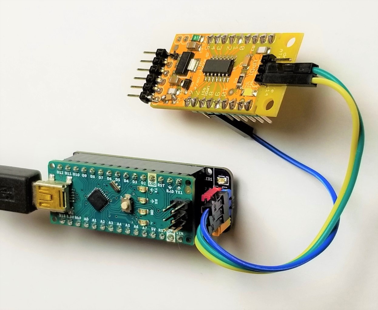
In May, Arduino released a guide on how you can create a UPDI programmer for under $10. Now Dlloydev has posted a guide on Github how to make an Arduino Nano HV UPDI programmer. The Nano HV UPDI programmer will enable you to use the additional configuration settings for the UPDI pin without the fear of getting locked out from the MCU. The Nano HV features 3 programming modes: UPDI, HV or PCHV, with the target voltage at 5V.
To get started, you have to install megaTinyCore, then Install the HV Programmer Firmware. After installation, you click on the green “Clone or download” button, then select “Download ZIP“. When you are through with the download, you unzip the file in a folder on your PC, then load the sketch “jtag2.updi.ino” into the Arduino IDE. Note that you have to uninstall the Write Protect jumper from the programmer for you to carry on with the project, the reason for this is that with a jumper installed, the auto-reset circuit of the programmer is disabled. This protects against accidental overwriting of the firmware and also ensures quick programming sessions by eliminating extra bootloader delays that would be caused by triggering the reset. Moving forward, from the IDE, you select Tools > Board > “Arduino Nano”. Then you select Tools > Port > (serial port used by the Nano). After that, you select Sketch > Upload.
When you are through with the upload, You have to install the Write Protect jumper. Finally, from the IDE, select Tools > Programmer > “jtag2updi (megaTinyCore)”. After going through all these processes, you can now use the Nano HV programmer to “Burn Bootloader” or to “Upload Using Programmer” from the Arduino IDE. However, you have to make sure to choose the appropriate board, chip, and port setting target. Then you can choose Programmer Mode Selection you want. To know if it is programming mode, the red and yellow LEDs will be ON. On startup, the yellow LED will indicate overload status. When the programming mode is set to HV or PCHV, bright blue LED flashes to indicate the HV pulse during programming of the target. On startup, the OVL sense analog input (A6) will be checked. If the voltage on A0-A5 (target power) has dipped below 90% (4.5V), then the yellow LED will indicate overload status by blinking at 4Hz. The user will then need to correct the problem and press reset to clear.
The programmer has three modes you can choose. They include:
- UPDI Mode: This mode would be used when the UPDI pin is configured as UPDI or for any target device that isn’t HV tolerant.
- HV Mode: This mode applies the 12V UPDI enable sequence (HV pulse) at the start of the programming sequence. This temporarily reconfigures the UPDI/Reset pin to UPDI mode which will remain in this state until the next POR. This allows programming to occur when the pin is configured as Reset. A power-on reset (POR) needs to occur for any fuse setting changes to take effect.
- PCHV Mode: Power Cycle High Voltage mode (PCHV) will initiate a power cycle and HV pulse at the start of the programming sequence. At the end of the sequence, a second power cycle will occur which causes any new fuse setting to take effect. The power cycle OFF duration has been set to 10ms. This mode would be used when the UPDI/Reset pin is configured as Reset or as GPIO.
In conclusion, this build enables you to create an Arduino Nano HV UPDI programmer with little resources, rather than having to spend many hundreds of dollars for a commercial one. You can get more information in the guide on Github.


