Electric Corkscrew Design Implementation
Author: Marian Hryntsiv, Senior Technical Documentation Apps Engineer, Renesas Electronics, Lviv, Ukraine The art of wine appreciation and the joy of opening a bottle have long been intertwined with using a corkscrew. Over the years, advancements in technology have revolutionized this process, bringing about the advent of electric corkscrews.
Author: Marian Hryntsiv, Senior Technical Documentation Apps Engineer, Renesas Electronics, Lviv, Ukraine
The art of wine appreciation and the joy of opening a bottle have long been intertwined with using a corkscrew. Over the years, advancements in technology have revolutionized this process, bringing about the advent of electric corkscrews. These innovative devices, powered by a motor, have streamlined the wine-opening experience, making it effortless, efficient, and enjoyable for wine enthusiasts and professionals alike. This article guides how to use the Renesas’ SLG47105 HVPAK so as to implement an electric corkscrew. However, you may download our free GreenPAK Designer software to open the .gp file and view the proposed circuit design. Use the GreenPAK development tools to freeze the design into your own customized IC in a matter of minutes.
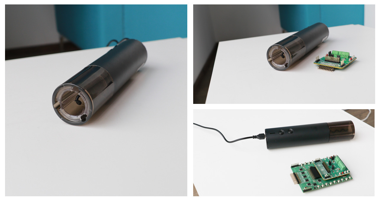
Brushed DC motors are used to implement the design. The motor driver plays a crucial role in them, providing the necessary torque, speed, and control required to perform the delicate task of removing the cork from the bottle.
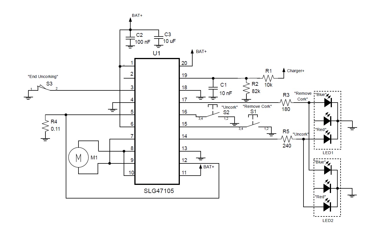
The Renesas’ SLG47105 HVPAK combines mixed-signal logic and high-drive H-/Half-Bridges and proves to be an ideal choice for implementing the functionality of an electric corkscrew. Figure 2 illustrates a general schematic of the device based on the HVPAK.
GreenPAK Design
Figure 3 shows an internal design of the electric corkscrew in the GreenPAK Designer software.
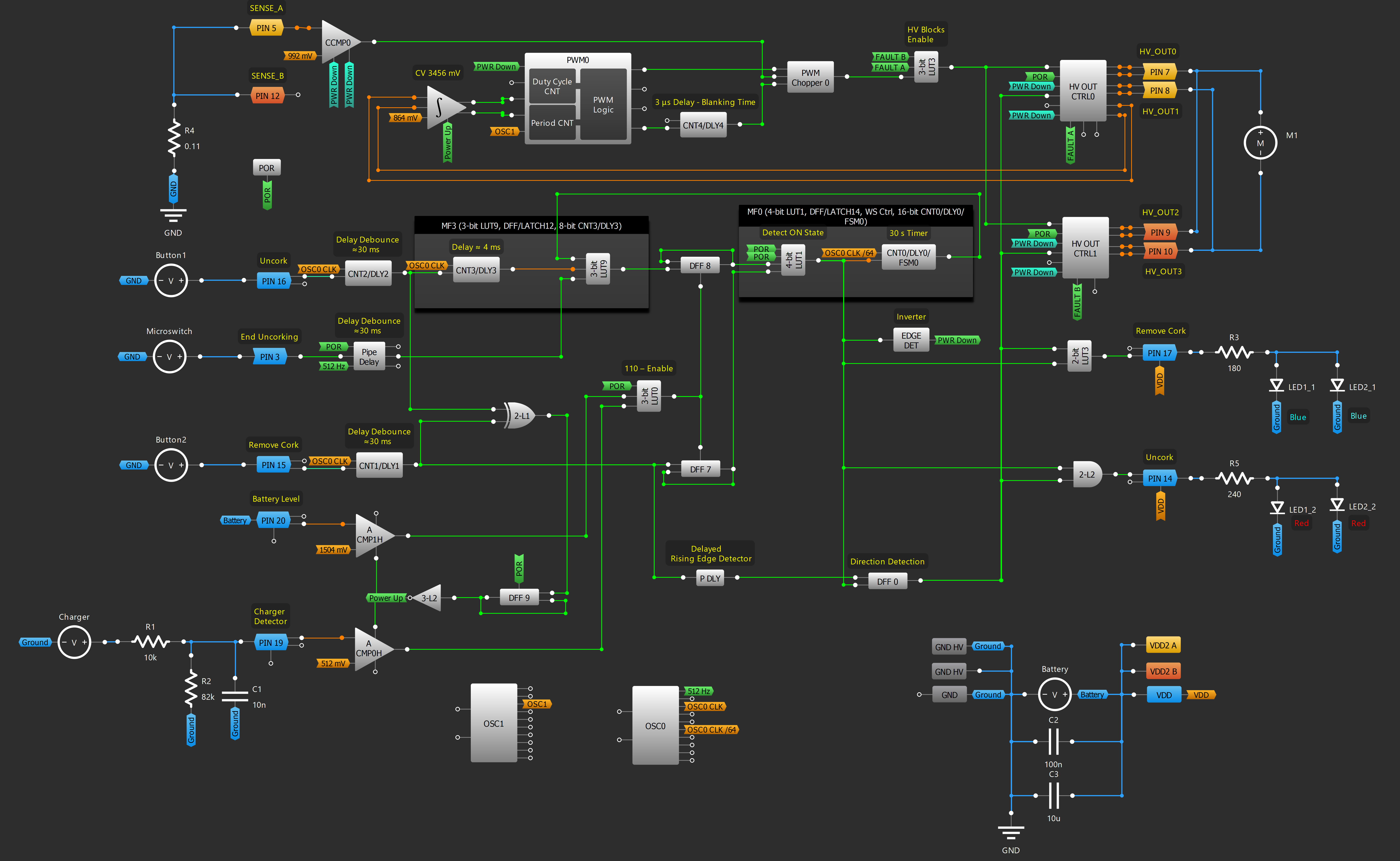
The main role in driving the motor is performed by high-drive pins 7, 8, 9, and 10 along with their corresponding control macrocells HV OUT Ctrl0 and HV Out Ctrl1. To increase the current rating, users have the option to connect the outputs in parallel, which was implemented in the corkscrew circuit.
Because the corkscrew needs to rotate in both directions, the macrocells HV OUT Ctrl0 and HV Out Ctrl1 are configured in Full-Bridge mode. By supplying a HIGH level signal from the POR (Power-On Reset) to the Decay inputs of HV OUT Ctrl0 and HV Out Ctrl1, a Slow decay mode is activated. This mode allows for a gradual reduction in an inductive current, resulting in a quick halt of the motor’s movement.
Current Regulation
In this design, a current control was used. The current control circuit is provided to regulate the system in the event of an overcurrent condition, such as an abnormal mechanical load on a DC motor. The current is sensed by an external sense resistor connected to the SENSE_A and SENSE_B pins. The resistor value is calculated using the formula:
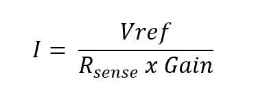
The current sense comparator (CCMP0) is used to convert the sense resistor current into a logic level, thus limiting the output current. In this case, Rsense was chosen to be equal to 0.11 Ω, Vref was set to 998 mV, and the gain was set to 4, resulting in a limiting current of 2.2 A. This current comparator signal is utilized by the PWM Chopper to chop the PWM duty cycle. By using the current comparator with the PWM block, the output current can be dynamically adjusted. The operational principle of the PWM chopper is illustrated in Figure 4.
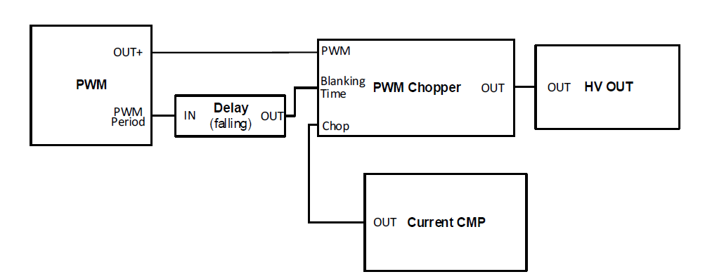
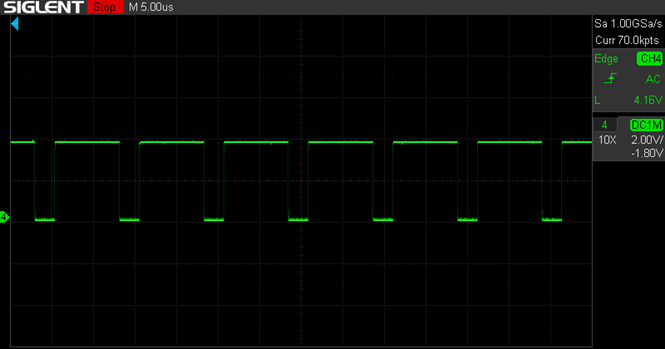
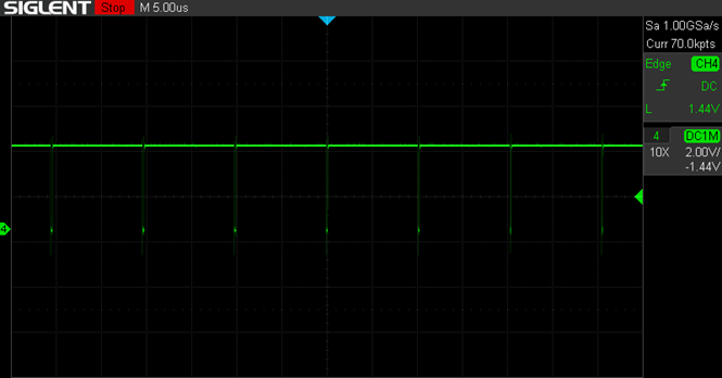
A delay allows us to ignore the Current Comparator signal during the Blanking time, which occurs during the motor start period. Any active signal from the Current CMP after the Blanking time causes the PWM Duty Cycle to be chopped to the end of the current period. Figure 5 demonstrates the PWM chopping process in the electric corkscrew.

Voltage Regulation
Because the device is powered by a lithium-ion battery, the PWM voltage regulation is useful for this design. It allows us to maintain a constant motor speed with a changeable power supply level. When the VDD is decreasing (the battery discharging), it becomes possible to increase the PWM duty cycle.
For the voltage regulation, the Differential Amplifier with Integrator and Analog Comparator macrocell is used. This macrocell monitors the voltage difference between HV_GPO0_HD and HV_GPO1_HD pins of the Full Bridge and integrates it to get an average voltage value. If the average output voltage is lower than Vref, the duty cycle of the PWM output needs to increase; if the average output value is higher than Vref, the duty cycle needs to decrease; when the average output value is equal to the comparator threshold, the PWM duty cycle is kept by EQUAL output. Figure 6, Figure 7, and Figure 8 show the voltage regulation process in the electric corkscrew.

The integrator reference voltage was set to 864 mV, resulting in a threshold of 3.456 V. This threshold value guarantees a constant voltage of 3 V across the motor winding, regardless of the battery voltage.
Motor Control Logic
When the user presses the “Uncork” button, a short LOW level pulse is generated at the output of Pin 16. To eliminate switch bouncing, a Delay macrocell DLY2 is used. In sleep mode, the output of the 3-bit LUT9 remains LOW. However, when any of the following events occurs: the “Uncork” button is pressed, the cork activates the microswitch, or the timer is triggered – the output transitions to a HIGH level. On the rising edge of this pulse, DFF8 changes its state to the opposite, resulting in a LOW level output. Subsequently, the output of the 4-bit LUT1 goes HIGH. This signal is fed to the Edge Detector macrocell that works as both edges delayed inverter. It activates the HV OUT control blocks and auxiliary macrocells, bringing them out of sleep mode and initiating the clockwise rotation of the motor. The 4 ms DLY3 is necessary to ensure that the comparators are powered up before the 3-bit LUT9 output signal reaches the CLK input of the DFF8.
Additionally, the rising edge of the signal from the output of 4-bit LUT1 is delayed by DLY0 for 30 seconds. If the corkscrew is not turned off within 30 seconds, this delayed rising edge signal reaches the input of the 3-bit LUT9, causing its output to go HIGH. This change in state forces DFF8 to switch its state, and the output of the 4-bit LUT1 goes LOW, resulting in the motor ceasing its operation. A similar sequence of events occurs when the cork is unscrewed to a sufficient extent to activate the microswitch (signaling the end of uncorking), which connects Pin 3 to GND. The 30-second timer function ensures that the motor shuts off and the corkscrew enters sleep mode for both the uncorking and cork removal modes. This shutdown function enables power conservation and prevents overheating.
When the user presses the “Remove Cork” button, DFF7 changes its state to the opposite, resulting in a LOW level output. Subsequently, the output of the 4-bit LUT1 goes HIGH, initiating the motor’s counterclockwise rotation. Similarly, to eliminate this switch bouncing, a Delay macrocell DLY1 is used. Furthermore, to eliminate microswitch bouncing, a Pipe Delay is employed.
P DLY macrocell that works as a delayed rising edge detector, paired with DFF0, is designed to detect which button was pressed. The signal from the output of DFF0 is fed to the PH inputs of the HV OUT Control blocks, determining the direction of motor rotation based on the button pressed. Specifically, if the output of DFF0 is LOW, the motor rotates clockwise, and if it is HIGH, the motor rotates counterclockwise.
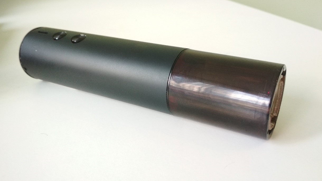
Depending on which button is pressed and if the corkscrew is in working mode, the 2-bit LUT2 and 2-bit LUT3 generate a HIGH level signal for one of the LEDs. The red LED illuminates when the output of the 2-bit LUT2 is HIGH (indicating the active uncorking mode), while the blue LED lights up when the output of the 2-bit LUT3 is HIGH (indicating the active cork removal mode).
Additionally, the corkscrew can be turned off by pressing either of two buttons while it is in working mode.
The 3-bit LUT0 enables DFF7 and DFF8 only if the following conditions are met: no charger is connected, the battery voltage is above 3 V, and the POR output signal is HIGH. The ACMP1 measures the battery level, while paneACMP0 detects the presence of a connected charger.
To ensure low energy consumption in sleep mode, the Differential Amplifier with Integrator and Analog Comparator macrocell, along with analog comparators ACMP0H and ACMP1H, are designed to exit sleep mode upon pressing any button. The signals from these buttons first pass through the 2-bit LUT1, which outputs a pulse for any change in its inputs. The DFF9 changes its state in response to this pulse. Subsequently, the signal is inverted and supplied to the power inputs of the comparators and the amplifier.
The 3-bit LUT3 enables the operation of HV OUT Control blocks if signals FAULT A and FAULT B are LOW (indicating no fault events).
Conclusion
This article explores the utilization of the SLG47105 HVPAK in a corkscrew implementation. This HVPAK is a versatile device that offers a wide range of mixed-signal functionalities combined with high-voltage capabilities, all packed into a compact and thermally efficient integrated circuit. With its abundance of digital and analog blocks, it can replace multiple ICs required for the corkscrew’s operation, including the motor driver, logic components, and a voltage monitor. Additionally, it provides features such as voltage and current control, along with advanced protection mechanisms against abnormal situations. The device is cost-effective and energy-efficient, making it an excellent choice.


