Simple fixture determines leakage of capacitors and semiconductor switches
The circuit in Figure 1a comprises a voltage follower, IC1 , and the reference-voltage source of IC2. IC1 is an Analog Devices AD8661 op amp, which has a guaranteed input-bias current of no more than 1 pA and a typical input-bias current of 0.3 pA (Reference 1), and IC2 is an Analog Devices ADR391 precision voltage reference (Reference 2).
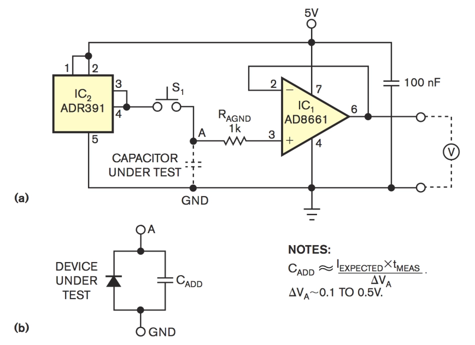
The circuit in Figure 1a comprises a voltage follower, IC1 , and the reference-voltage source of IC2. IC1 is an Analog Devices AD8661 op amp, which has a guaranteed input-bias current of no more than 1 pA and a typical input-bias current of 0.3 pA (Reference 1), and IC2 is an Analog Devices ADR391 precision voltage reference (Reference 2). The manufacturer trims the input offset voltage of this op amp not to exceed 100 µV, and the typical value is 30 µV. These properties suit this amplifier for observing self-discharging of almost any type of capacitor. The leakage currents of solid-tantalum capacitors and those having high-quality plastic dielectrics are well above the input-bias current of voltage follower IC1. The CUT (capacitor under test) initially charges to the reference-voltage level of 2.5V by connecting Point A to the output of IC2. Subsequently, at some convenient time, Point A disconnects from the source of the reference voltage. A DVM (digital voltmeter) measures the output voltage of the follower at some reasonable time.
Simple fixture determines leakage of capacitors and semiconductor switches – [Link]


