TP4056 3V3 Load Share Upgrade
A lot of project are battery powered and some of them need dual battery links. Robert on hackaday.io had shared his new project that shed light on this issue.
A lot of project are battery powered and some of them need dual battery links. Robert on hackaday.io had shared his new project that shed light on this issue. He built an load sharing addon board with the ability to charge the battery while the project is operating.
Many Chinese charger boards are out there based on TP4056, but these boards don’t have the load sharing or voltage regulator features.
Load sharing means that you can power your circuit in two ways, from battery and from Vcc if a charger is connected. Once the charger is connected the battery will start charging and the load will be powered directly from Vcc. Robert added this feature to a recent design and also he added voltage regulation by using MCP1252.
The Components needed to build this project:
- 1x MCP1252-33X50/MS Power: Management IC / Switching Regulators
- 1x FDN304P: Discrete Semiconductors / Diode-Transistor Modules
- 1x SGL1-40-DIO: Schottky diode
- 2x 100k 1206 resistor
- 3x 10uF 1206 capacitor X7R
- 1x 2.2uF 0805 capacitor X7R
- 1x ON/OFF switch (optional)
- 2x 2 pin pcb connector
- 1x PCB from OSHpark
This schematic was inspired by multiple designs and modified by Robert.
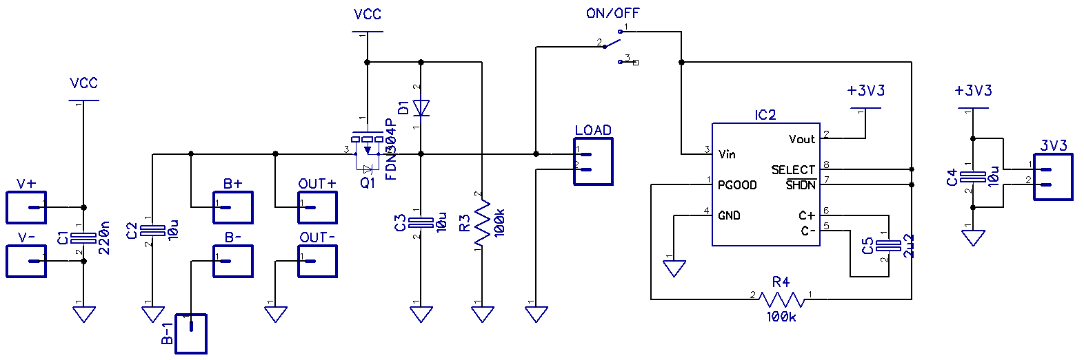
“The advantage of MCP1252 is automatic buck/boost feature, it will maintain the regulated output voltage whether the input voltage is above or below the output voltage (2.1 to 5.0 V input range) so it is ideal for the lithium battery voltage. If you read the datasheet for the MCP1252-33X50I/MS there is clearly specified what type of MLCC capacitor should be used.”
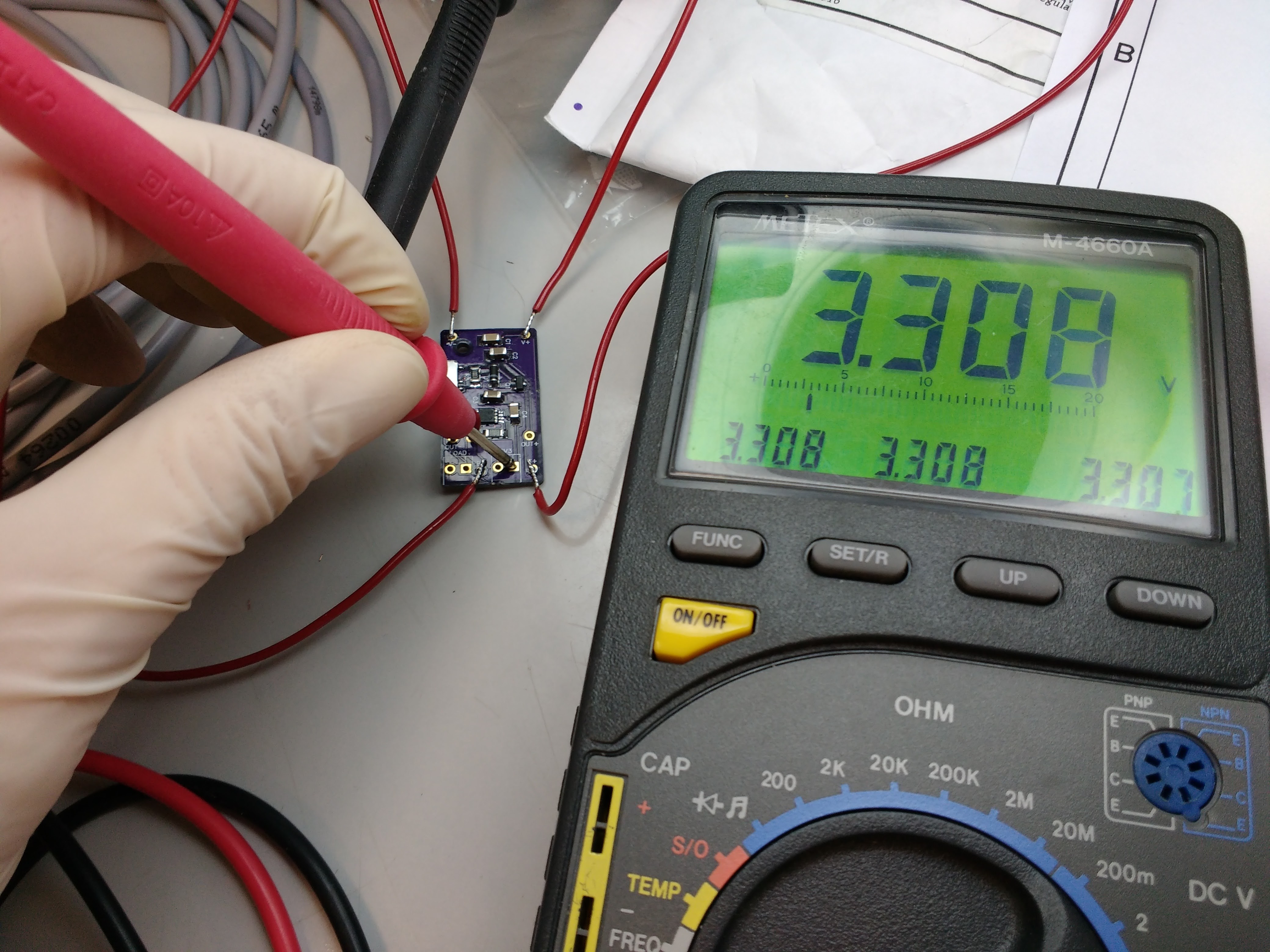
The maximum output current of this board is 120mA and the output voltage is 3.3 V. It may sound not that suitable for your projects if you want to power an ESP8266, but still you can build your own board with different components to achieve the outputs you need. For example, by using MCP1253, which is identical to MCP1252, you will get higher switching frequency (1MHz). Robert’s plan is to use this board with CO2 sensor (about 30 mA) and other low power sensors, some MCU and LCD, which can be powered using 120 mA.
Some measurements will be done to test the functionality of this board. To keep updated with the news of this project, you can follow the project on hackaday.io. You can also check other projects by Robert here.


