Voltage-Controlled Pulse Width Modulator (PWM) – PWM Signal Generator
This is an easy-to-use voltage to PWM converter. The project occupies very little space.
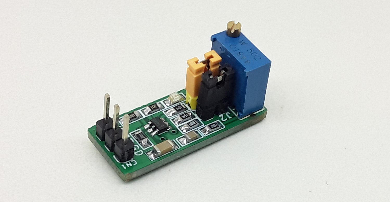
This is an easy-to-use voltage to PWM converter. The project occupies very little space. The circuit is built using the versatile silicon timing device LT6992-1 chip. Pulse Width Modulation (PWM) Controlled by Simple 0V to 1V Analog Input, multiturn trimmer potentiometer provided to adjust the duty cycle 0 to 100 %. The circuit also has provision to set the frequency to 2.65Khz, 7.8Khz, 10.7Khz or 15.7Khz using jumper J1 and J2. Circuit operates with a 5V Supply. D1 is a power LED, all connections are made easy using the 3 pin male header connector CN1. This is a very useful tool as test gear or to drive various circuits that require a PWM signal. The output frequency is very accurate and steady has 1.7% Maximum Frequency Error. CMOS Output Driver Sources/Sinks 20mA
Voltage-Controlled Pulse Width Modulator (PWM) – PWM Signal Generator – [Link]


