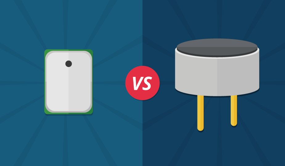
Comparing MEMS and Electret Condenser Microphones
MEMS Microphone Basics MEMS microphones are constructed with a MEMS (Micro-Electro-Mechanical System) component placed on a printed circuit board (PCB) and protected with a mechanical cover. A small hole is fabricated in the case to allow sound into the microphone and is either designated as top-ported if the hole is in the top cover or bottom-ported if the hole is in the PCB.
MEMS Microphone Basics
MEMS microphones are constructed with a MEMS (Micro-Electro-Mechanical System) component placed on a printed circuit board (PCB) and protected with a mechanical cover. A small hole is fabricated in the case to allow sound into the microphone and is either designated as top-ported if the hole is in the top cover or bottom-ported if the hole is in the PCB. The MEMS component is often designed with a mechanical diaphragm and mounting structure created on a semiconductor die.
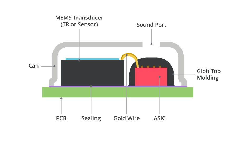
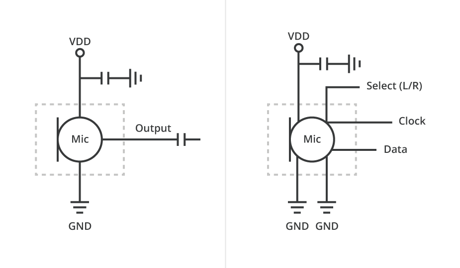
The MEMS diaphragm forms a capacitor and sound pressure waves cause movement of the diaphragm. MEMS microphones typically contain a second semiconductor die which functions as an audio preamplifier, converting the changing capacitance of the MEMS to an electrical signal. The output of the audio preamplifier is provided to the user if an analog output signal is desired. If a digital output signal is desired, then an analog-to-digital converter (ADC) is included on the same die as the audio preamplifier. A common format used for the digital encoding in MEMS microphones is pulse density modulation (PDM), which allows for communication with only a clock and a single data line. Decoding of the digital signal at the receiver is simplified due to the single bit encoding of the data.
Electret Condenser Microphone Basics
Electret Condenser Microphones (ECM) are constructed as shown in the figure below.

An electret diaphragm (material with a fixed surface charge) is spaced close to a conductive plate, and similar to MEMS microphones, a capacitor is formed with the air gap as the dielectric. Voltage across the capacitor varies as the value of the capacitance changes due to sound pressure waves moving the electret diaphragm, ΔV = Q/ ΔC. The capacitor voltage variations are amplified and buffered by a JFET internal to the microphone housing. The JFET is typically configured in a common-source configuration, while an external load resistor and dc blocking capacitor are used in the external application circuit.
By Bruce Rose, Principal Applications Engineer, CUI @ www.cui.com


