Active Rectifier Controller with Reverse Protection for Battery and Solar cell
This demonstration circuit is an active rectifier with reverse protection for batteries in automotive applications. The project is designed for 5A load current.
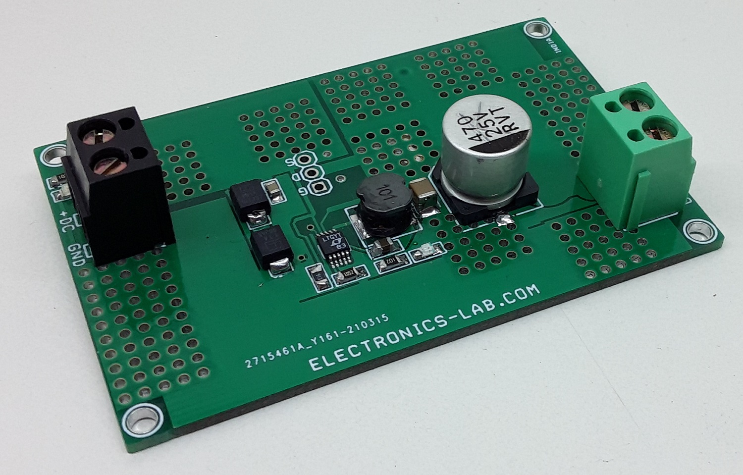
This demonstration circuit is an active rectifier with reverse protection for batteries in automotive applications. The project is designed for 5A load current. Two clamping diodes, D1 and D2, are used on the board to protect the IC from overvoltage spikes at the input. The input supply range is 12V to 24V. The active rectifier controller chip LT8672 controls an external N-channel MOSFET (Q1) to form an ideal diode. The GATE amplifier senses across DRAIN and SOURCE and drives the gate of the MOSFET to regulate the forward voltage to 20mV. As the load current increases, GATE is driven higher until a point is reached where the MOSFET is fully on. If the load current is reduced, the GATE amplifier drives the MOSFET gate lower to maintain a 20mV drop. If the voltage VDRAIN is reduced to a point where a forward drop of 20mV cannot be supported, the GATE amplifier drives the MOSFET off.
Active Rectifier Controller with Reverse Protection for Battery and Solar cell – [Link]


