A Simple Miniature Digital Storage Oscilloscope powered by an STC MCU
For makers and electronics engineers, the oscilloscope is one of the most important tools in the lab. It is a test instrument for visualizing and observing various signals usually as a two-dimensional plot of signals against time.
For makers and electronics engineers, the oscilloscope is one of the most important tools in the lab. It is a test instrument for visualizing and observing various signals usually as a two-dimensional plot of signals against time. Apart from being used to view and compare waveforms in the design and debugging of electronic systems, the oscilloscope is also very useful in determine voltage levels, frequencies, and other signal parameters as they change with time. However, most of the oscilloscopes available today are quite expensive, be it small or advanced.
In a bid to make things easier, several projects are beginning to show up on how someone, with the right tools, can create cheap and compact oscilloscope that will do the job for hobby tasks. One of such is CreativeLau’s build that puts a tiny Digital Storage Oscilloscope within your reach.
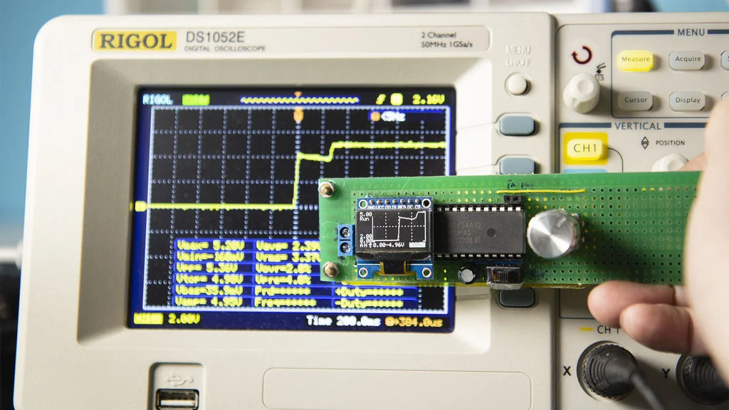
Following an earlier release on how to make an STC-powered function generator on his YouTube channel, maker Creative Lau has published another DIY guide, this time on how to easily build a simple miniature digital storage oscilloscope with a DIP-packaged STC8A8K64S4A12 microcontroller unit for basic engineering needs.
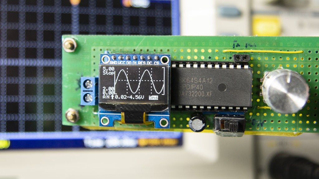
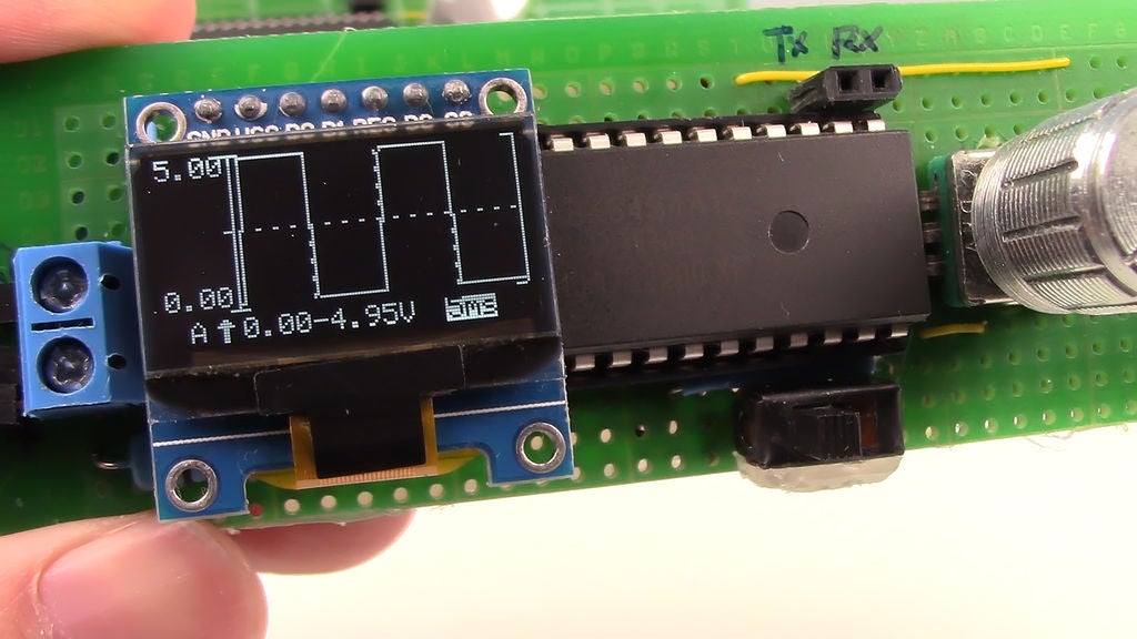
“This is a simple oscilloscope made with STC MCU. You can use this Mini DSO to observe waveforms with a time interval of 100us – 500ms, the voltage range of 0-30V, and a draw mode of vector or dots” says Lau as he writes about his project.”
Lau’s build goes hand in hand with the STC-powered function generator. It is simple, cheap, and easy to assemble. The only limit is that it is still unable to read voltages lower than zero; it’s readings automatically stop at zero no matter how low the voltage goes.
Video
Apart from the STC8A8K64S4A12 microcontroller, the other components used for the build include a compact SSD1306 OLED display, a 5V booster module, one 3.7V Li-ion battery pack for portability as well as a rotary EC11 encoder and Tact switch for user interface and power on/off. Others include one four resistors and two capacitors (47uF and 0.01uF).
Meanwhile, Lau claims that the build is still being worked on and hopes to share updates on it as soon as he is done.
“The new functions for the Mini DSO are being developed. They are Normal Sweep and Single Sweep. With these functions, you could observe the waveform mutation” Lau explains.
More details of this build can be found on Instructables including the schematics and circuit design attached under the download section of the site.


