Temper: Sleek temperature sensor built on ESP8266
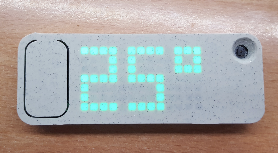
Meet Temper, a compact, low power temperature sensor based on ESP8266 and SHT30 with a large 13x7 pixel led display. It accesses WiFi periodically to display temperature and humidity data as well as battery percentage via the MQTT protocol.
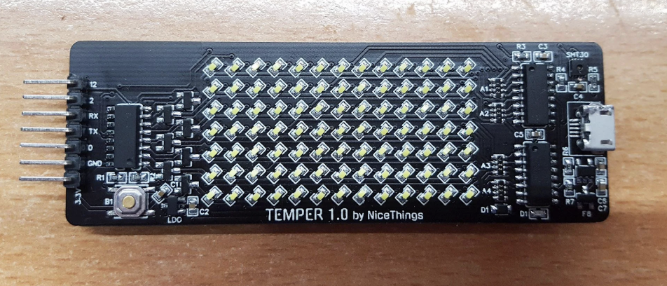
Meet Temper, a compact, low power temperature sensor based on ESP8266 and SHT30 with a large 13×7 pixel led display. It accesses WiFi periodically to display temperature and humidity data as well as battery percentage via the MQTT protocol. The device’s display uses three 74HC595 + 7 n-fets, TP4054 to handle battery charging through a USB and MCP1700T LDO to power the ESP.
For WiFi setup, Temper comes with a super simple Web config interface and is also compatible with a home assistant and it’s auto-discovery feature. It can also be used with any platform that supports MQTT and can be attached to walls using magnets.
The case for the device is a stone-age light (PLA) from Spectrum filaments. It comes with a large reset button on the left forces the device to request MQTT temperature data and displays it within 5s after the button press.
Explaining the design, Martin Černý said:
“The ESP is set to wake up every hour to send the temperature to MQTT. Pushing a button (hard resetting it) will show the temperature on the display and battery status as well. It should be able to make half a year of battery life or more (during deep sleep, it draws 32uA which is beyond awesome). This, of course, is not perfect and an e-ink display would make more sense to keep the values visible but also would quadruple the cost of the thing (but I ordered some e-inks anyway :D).”
He also notes that:
“There is a simple battery sensing onboard to keep an eye on battery level. Battery sensing is also used as a trigger for the config portal as there was not enough place for more buttons. How it works is after each button push (hard reset), it will check the battery level. If the battery level is above the threshold, it will start the configuration access point (for wifi settings, MQTT, etc.).”
Martin says he won’t be selling Temper himself, stating that they are “overwhelmingly time-consuming” to make by himself. However, the firmware and documentation are neatly documented on Github with some more helpful information on the wiki.
To put the project together you will the items listed below along with some experience with hot air soldering/ reflow oven.
- Hot air station and/or reflow oven (SHT30 has pins at the bottom, that can’t be hand-soldered)
- Components listed in the “PCB and BOM” directory of the GitHub repo.
- The plastic case.
- Hot glue to fixate PCB in the enclosure.
- Some Patience
You will notice on the board that the GPIO2 and GPIO12 are broken out, GPIO12 is safe for any use, but GPIO2 has to be pulled high on startup or the ESP won’t boot up correctly.
More information on the project and it’s build instructions can be found on its GitHub project page.


